
11/05/2015
I often witness end users operating pumps to the left side of the curve, away from the best efficiency point (BEP) and near shutoff. This is not the ideal area because of issues with shaft deflection, cavitation and recirculation, all of which lead to a reduction in pump reliability. There are several other reasons to avoid operating in this region as well.
Minimum Flow
Minimum flow is the operating area where centrifugal pumps will quickly get into trouble. The power introduced into a pump by the driver will manifest as energy or work—either as a useful flow with a corresponding head or as heat, vibration, noise (acoustic energy) or a combination of all these. Because no pump is 100 percent efficient, the energy not used in the work for the head and flow will show up as one of these other items. Technically, four factors affect minimum flow: fluid temperature rise, minimum stable flow, internal recirculation and thrust capacity. For most cases, we can simplify these factors and just look at two main areas. The first area is under the category of mechanical issues, and the other is thermal issues. A minimum continuous flow rate for a pump should be determined for mechanical and thermal factors. The higher of the two becomes the minimum flow rate for that pump.Mechanical Issues
When the pump is operated away from BEP, the radial thrust will increase dramatically. For a single volute pump, it is close to a hyperbolic function. The shaft will deflect and create issues with the bearings and seals, dramatically shortening their useful life. Also, the flow velocity (angle/profile) will not match the impeller vane speeds (velocity/inlet angle/angle of incidence), and suction recirculation will occur, creating fluid stalls and cavitation. The shaft deflection ratio (L3/D4) comes into play in these calculations: A low L3/D4 ratio will mitigate the deleterious effects.Calculating MCSF
Minimum continuous stable flow (MCSF) is defined as the flow rate below which the pump should not be operated. The American Petroleum Institute (API) will define it as operating without exceeding specified vibration limits. The actual calculation of this MCSF rate is a function of numerous factors that include suction energy (in my opinion, suction energy is otherwise an outdated concept), suction-specific speed and specific speed (impeller geometries). Pay particular attention to factors that affect the onset of suction recirculation and exit turbulence at the vane tips as these result in vortex cavitation. Some specifications tend to simplify these calculations and state that minimum flow should be a percentage of the BEP flow rate. For example, API 610 states that MCSF will be no less than 60 percent allowable value (70 percent is preferred). ANSI B73.1 states in paragraph 5.1.6 that "pumps shall be designed to operate continuously between 110 percent of BEP and the minimum flows shown in Table 5." There is more to this specification, which I will not cover here, but please note that Table 5 values do not take thermal flow factors into consideration.Thermal Considerations
While the energy put into a pump running at minimum flow (for other than head and flow) may yield vibration and noise, it is most likely to manifest as heat. Another possibility is heating the fluid to the point of vaporizing the fluid and cavitating or even exceeding the design limits of the casing (due to the vaporization of the fluid to a gas and causing casing rupture). The rate at which the temperature will rise in a pump with a closed discharge valve can be calculated using Equation 1.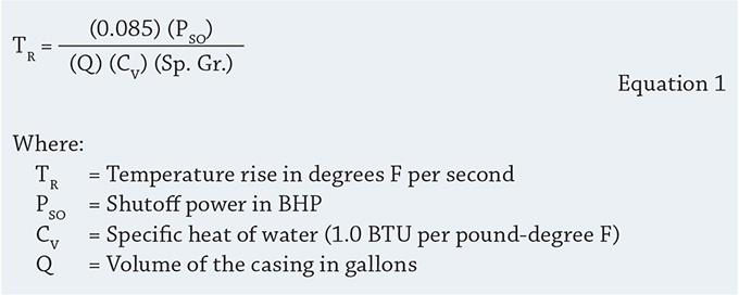
MCTF
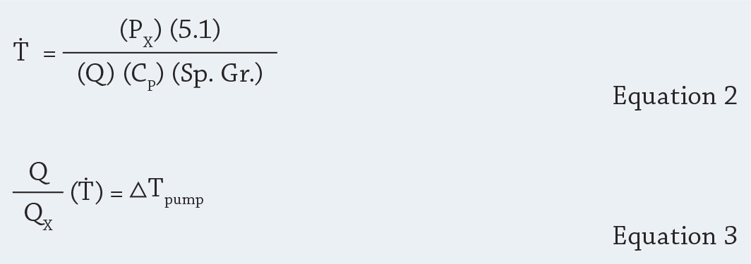
Minimum continuous thermal flow (MCTF) is usually not the most limiting factor in determining a pump's minimum flow. Typically the mechanical aspects will be the limiting factor, but do not ignore the thermal flow considerations. First, you need to know the saturation temperature for the fluid you are pumping. You should already know this value because you already completed the net positive suction head available (NPSHA) calculation. Then determine the temperature of the fluid as it is entering the pump. The difference between these two temperatures is your maximum allowable ∆T. The Pump Handbook (Igor J. Karassik, Paul Cooper et al.) recommends you give at least a 15-degree F margin (9 degrees C). Subtract that from your original ∆T number to arrive at the new value with a safety margin. Then using the following equations (see Equations 2 and 3), first calculate different temperature rises in the pump until you arrive at the number that no longer exceeds the maximum allowable temperature rise previously calculated. I suggest you start with flows that are around 10 percent or better of BEP flow. In Equation 2, PX is the power at the flow you selected (in BHP).Do not confuse with PSO from Equation 1, which is the shutoff power. Q X is the flow rate (in gallons per minute) through the pump at the flow you selected and ∆T will equal the fluid temperature rise. Metric friends can drop the value 5.1. The flow rate is liters per second, power is in kW, the casing volume is in liters and temperatures are in Celsius. CP is the specific heat for the fluid and Q is the casing liquid volume. Sp. Gr. is the specific gravity. If the temperature rise you calculate at 10 percent of BEP flow is less than the maximum allowable temperature rise calculated earlier, then use 10 percent of BEP flow as the minimum continuous thermal flow. You should always operate the pump in a region of best efficiency and the least amount of cavitation, vibration, noise and heat generation. If this is not feasible, then change something with the pump and/or the system. Otherwise, you will reduce the reliability of the pump and increase costs.See other articles in this series here.
