

In last month’s article, we discussed the four basic components found in every mechanical seal, as well as reviewed the different configurations seals typically are available in. This month’s article will look more closely at how a mechanical seal functions, and it will also identify some features to consider when selecting or being offered a seal from a supplier. First, we will look at how a mechanical seal “seals.”
The first misconception many seal users have is that a mechanical seal is leak free while in normal operation; this is not correct. As described in last month’s article, mechanical seals are precision, dynamic devices. The primary sealing interface, where the rotating face contacts the stationary seal face (Image 1), must be lubricated and cooled or significant heat and wear will occur quickly, resulting in catastrophic failure.
The reality is there is a small gap formed between the seal faces in which fluid under pressure and temperature will act to cool and lubricate the face pair. In aqueous fluid, this gap can be as small as 0.3 micrometers (µm). As the fluid migrates through the gap, its pressure will drop and the temperature will increase until it typically vaporizes and is not visible to the human eye. However, in some cases with higher viscosity fluids like oils, the fluid may not vaporize and the faces may appear wetted or even have a small drop occurring over time. In both cases, the mechanical seal is operating fine. Image 2 shows this process underway in an operating seal. Therefore, all seals must leak in order to operate properly.
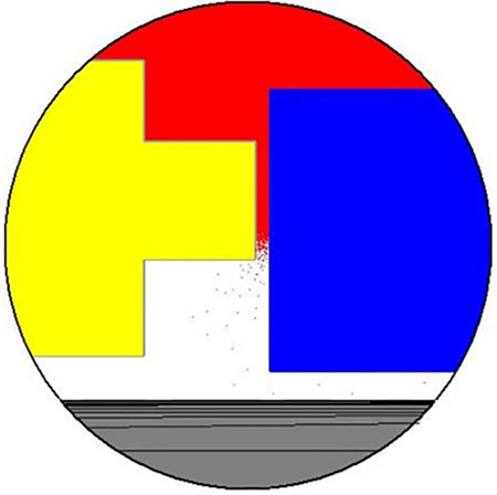
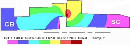
The seal faces do not run completely parallel as shown in Image 2, but due to the various stresses encountered in operation, there is always a level of distortion that is occurring. The art of mechanical seal design is to try to balance these various distortions so that at the design operating parameters, the faces are operating as close to parallel as possible and as close together as possible to limit the amount of leakage that occurs. Image 3 shows the results of a finite element analysis (FEA) model, showing the distortion occurring due to pressure and thermal stresses in an operating seal face pair.
It is critical to remember that if the sealed fluid does not offer the seal faces the proper amount of cooling and lubrication required, an external liquid or gas will need to be provided through what is called an environmental control/seal support system. The American Petroleum Institute (API) 682 Standard “Pumps—Shaft Sealing Systems for Centrifugal and Rotary Pumps” offers a complete list with diagrams for the various piping plans that can be used. Most mechanical seal manufacturers have API piping plan details on their websites as well.
If there are particulates in either the process stream or fluid being used to provide cooling and lubrication to the seal, additional action may need to be taken to limit or remove these particulates, as they can both clog the seal from operating properly or interfere with the cooling and lubrication the seal faces need.
Now that we know how a mechanical seal “seals,” it is important to understand what makes a mechanical seal successful in a given application. This starts with looking at what the goals are for the seal designer. This is fundamentally simple, but significantly more difficult to achieve in real life:
- To keep the seal face pair as flat and parallel as possible
- To keep the seal face pair as close together as possible to limit the amount of leakage occurring
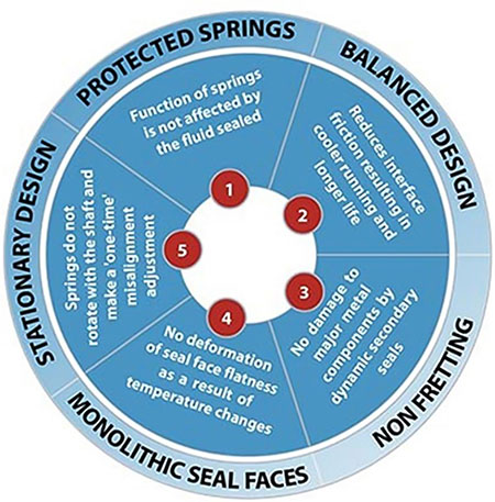
There are several approaches to this goal that different seal designers (manufacturers) will use. Here are five key features that should be focused on.
1. Protected Springs
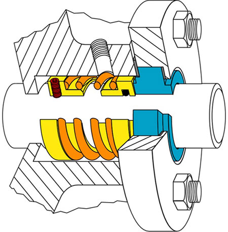
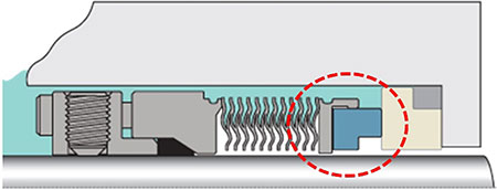
Many early seal designs position the spring(s) on the rotating portion of the seal. This is known as a rotary seal design (Image 5). As can be seen in Image 5, the spring(s) are exposed to the process fluid where they have the potential for chemical attack or clogging.
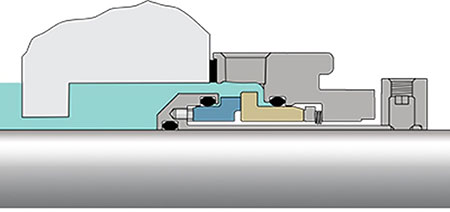
Recognizing these potential issues, seal designers developed a design that protects the springs by isolating them from the process fluid as shown in Image 6.
2. Balanced Design
Mechanical seal balance is a topic that could consume this entire article on its own. To simplify, seal balance describes the amount of hydraulic force (load) being applied to the seal faces. The higher the face loads, the greater the distortion and heat that is generated in the sealing interface, which works in direct opposition to the stated design goals above and also defines the operating capabilities of the mechanical seal. An unbalanced seal will have lower performance limits than a balanced seal design. An unbalanced seal design is one in which the full stuffing box pressure is impacting the loading on the seal faces as shown in Image 6.
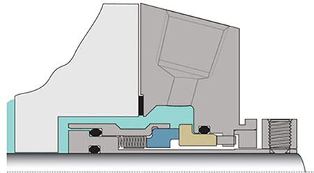
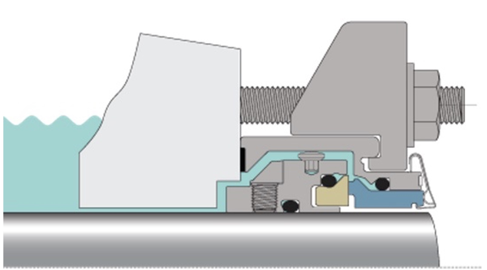
A balanced seal design is one in which only a portion of the sealing interface is exposed to the stuffing box pressure as shown in Image 7. By reducing the hydraulic loading on the sealing interface, the seal can operate at higher pressures, temperatures and speeds more reliably.
A mechanical seal’s balance is defined by what is known as its balance ratio, which is a calculation of the ratio between the closing forces imposed on the sealing interface versus the countering opening forces. A seal is considered unbalanced if this ratio is greater than 1.0. A standard balanced seal design will have a balance ratio between 0.65 and 0.85. However, for specific applications, a seal design can utilize different ratios to optimize the design.
3. Non-Fretting Design
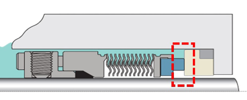
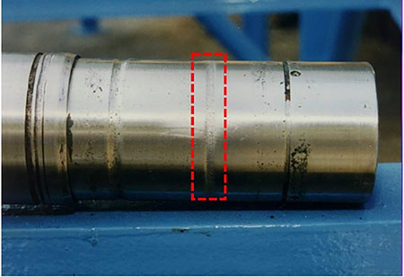
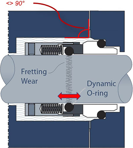
Image 8 shows a pump shaft sleeve with a small groove worn in the area where the seal’s dynamic elastomer is located. This occurs in rotary seal designs because nothing is perfectly aligned and concentric, so the rotary seal face will move relative to the stationary seal face. This very small movement results in the dynamic elastomer (O-ring, boot or bellows) rocking back and forth, causing the wear shown. If this continues for a period of time, the groove can become deep enough to inhibit the dynamic tracking required to maintain a small gap between the faces during operation, resulting in increased leakage. Image 9 shows this process.
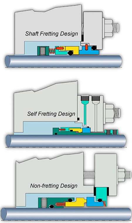
Seal designers have three options regarding the placement of the dynamic elastomer shown in Image 10. Originally, the dynamic elastomer was positioned directly on the pump’s sleeve or directly on the shaft, which resulted in the damage shown above. To combat this, seal designers can move the dynamic elastomer into the mechanical seal itself, but this just moves the wear internally to a metallic surface in the seal where it will still create problems. Alternatively, the seal designer can place the dynamic elastomer in a place where it does not contact any metallic surfaces, resulting in a non-fretting design.
4. Monolithic Seal Faces
Many first- and second-generation seal designs incorporated what is called composite seal face technology. This is defined as a sealing material inserted or embedded into a metal holder, typically stainless steel, or the alloy the seal metal parts are made of. Image 11 shows a seal design with a composite seal face.
In the 1990s, the third generation of seal design was introduced, including the use of monolithic seal face technologies. This means the entire seal face is made of one material like carbon/graphite, silicon carbide or tungsten carbide. Image 12 shows a monolithic seal face.
The major advantage of a monolithic seal face design relates to thermal growth. In the composite face design, there are two different materials which have different coefficients of expansion. In hotter processes, the materials will grow at different rates, resulting in additional face distortions which can limit the seals’ ability to provide adequate leakage control both during and after operation. Image 13 shows the distortions a composite face goes through in normal operation.
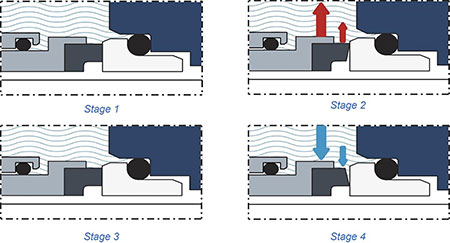
Stage 1 represents the seal installed in the pump before operation begins. As the seal begins to rotate (Stage 2), temperature begins to increase and the various materials begin to expand at different rates, resulting in face distortion. As the system reaches equilibrium, the seal face will stabilize as well, including wearing in (Stage 3). When the pump is shut down (Stage 4), all the components begin to cool off, resulting in the components returning to their original shape except for the seal face, which can lead to an increase in seal leakage. Unlike a composite face design, a monolithic seal face will return to its original shape, offering greater reliability and leakage control.
5. Stationary Seal Design
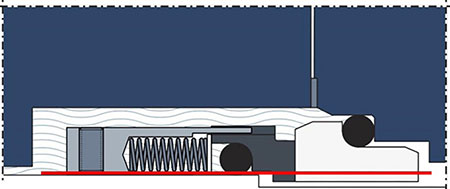
A stationary seal design is one where the springs are mounted in the stationary side of the mechanical seal as shown in Image 14. The advantage a stationary seal design offers is that when there is any static misalignment, the stationary springs must move once to align the stationary face to the rotary face.
Conversely, in a rotary seal design, the spring must actuate twice for every shaft rotation to maintain dynamic tracking. Therefore, if the pump is operating at a nominal 1,800 rotations per minute (rpm), the rotary springs and face are moving 3,600 times per minute. For a nominal 3,600 rpm application, the rotary components are moving 7,200 times per minute. If anything interrupts this motion, there will be a momentary opening of the seal faces, causing increased leakage. If there are particles present, offering the possibility of trapping particles between the faces causes increased leakage, face wear and damage.
Given this amount of internal motion, there is an opportunity for something to interrupt the dynamic tracking, resulting in a momentary “opening” of the sealing interface and resulting in increased leakage. This also offers an opportunity for dirt or other debris to lodge between the faces, resulting in increased wear and damage.
