

The Importance of Maintenance
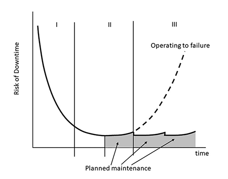
Routine maintenance is critical for rotating equipment and makes economic sense. For most pump applications, running a pump to failure leads to expensive repairs that require more time at the repair shop. If the pump service is critical, like a boiler feed pump, the failed pump may leave the plant at risk for reduced production or complete shutdown. In the case of a power plant, this lost production could result in hundreds of thousands of dollars in lost earnings. Knowing the condition of the plant’s pumps allows users to anticipate what pump maintenance is required for optimal operation. If the risk of failure over the life of a pump is considered, the initial installation is the period with the highest risk (phase I in Image 1). However, after successfully commissioning the pump and the system, the risk of failure drops to a low and reasonable level unless the pump is not maintained. In that case, the risk of failure increases with time, putting operations at risk for a pump failure.
Routine Maintenance & Monitoring
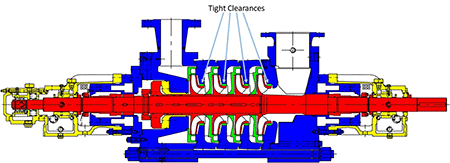
Reading and following the OEM’s operating and maintenance manual recommendations is best practice. Proper installation and routine maintenance requirements can be found in a good manual. Manual details include installation requirements for the pump baseplate and systems that support the pump operation, such as forced oil lubrication systems and cooling water requirements. Support for the suction and discharge piping connections is also critical. Loads on the pump nozzle distort the pump casing and can affect alignment. Inside a pump, there are tight clearances between rotating and stationary parts, and nozzle load-induced casing distortion will reduce those clearances even further (Image 2). Even for a pump that has been installed for years, the installation needs to be checked to ensure the piping nozzles still align with the pump nozzles.
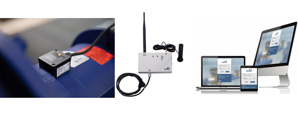
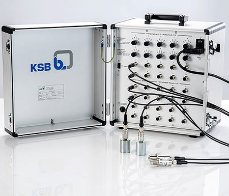
Monitoring bearing temperatures and bearing housing vibration level is more than enough for most installations. While shaft position monitoring with proximity probes is great, a simple seismic vibration sensor is sufficient for many installations. Fortunately, many wireless monitoring systems are available if users do not have monitoring systems in place (Image 3).
Recommendations for routine maintenance are an essential part of the OEM’s manual. Maintenance recommendations will often include recommended intervals for checking or changing lubrication. They also include the expected intervals for checking wear parts such as bearings and shaft seals. The manual provides guidelines on the number of hours the pump can be expected to operate before users need to plan scheduled maintenance. However, this recommendation is an estimate for many clean liquid applications. The intervals between needed repairs at a plant will depend greatly on how the pump is operated. Pumps operating continuously at a flow rate close to their best efficiency point may not require a rebuild until well beyond the OEM rebuild interval, which is a conservative average. The other extreme is a pump that operates intermittently at an extremely low flow rate. When pumps operate at these low flow rates, a large percentage of the pump’s absorbed power does nothing but create heat and vibrations, which accelerates pump wear and requires more frequent pump rebuilds. For example, if a pump operates at 50% efficiency, half of the pump input power only generates heat and creates vibrations.
Pump Efficiency & System Interaction
If users have a pump that is operating at extreme part load or suspect that the pump operation may not be ideal, then it is important to understand how the pump is operating in the system.
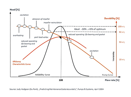
To see if the pump is being operated in a way that might shorten its life, the key pump performance parameters need to be monitored and compared to the pump performance curve. This would include pump flow, suction and discharge pressure, inlet temperature and rotating speed. Plotting the actual pump operating points on the pump curve will tell a user where the pump is operating relative to its best efficiency point. This will allow users to determine if the pump’s operation is ideal or harsh (Image 4).
Operations with limited pump and system instrumentation or limited pump expertise can look to certain companies for assistance. Some companies have portable dataloggers and personnel who can monitor a system for a period of time, generate a comprehensive report outlining how the pump is functioning and provide possible solutions for optimization.
The Pump Health Check
Monitoring the bearing temperatures and vibration levels is helpful and recommended, but how can users determine when to plan a pump rebuild without sending the pump to a repair shop?
For some pump designs, there is a solution referred to as a pump health check.
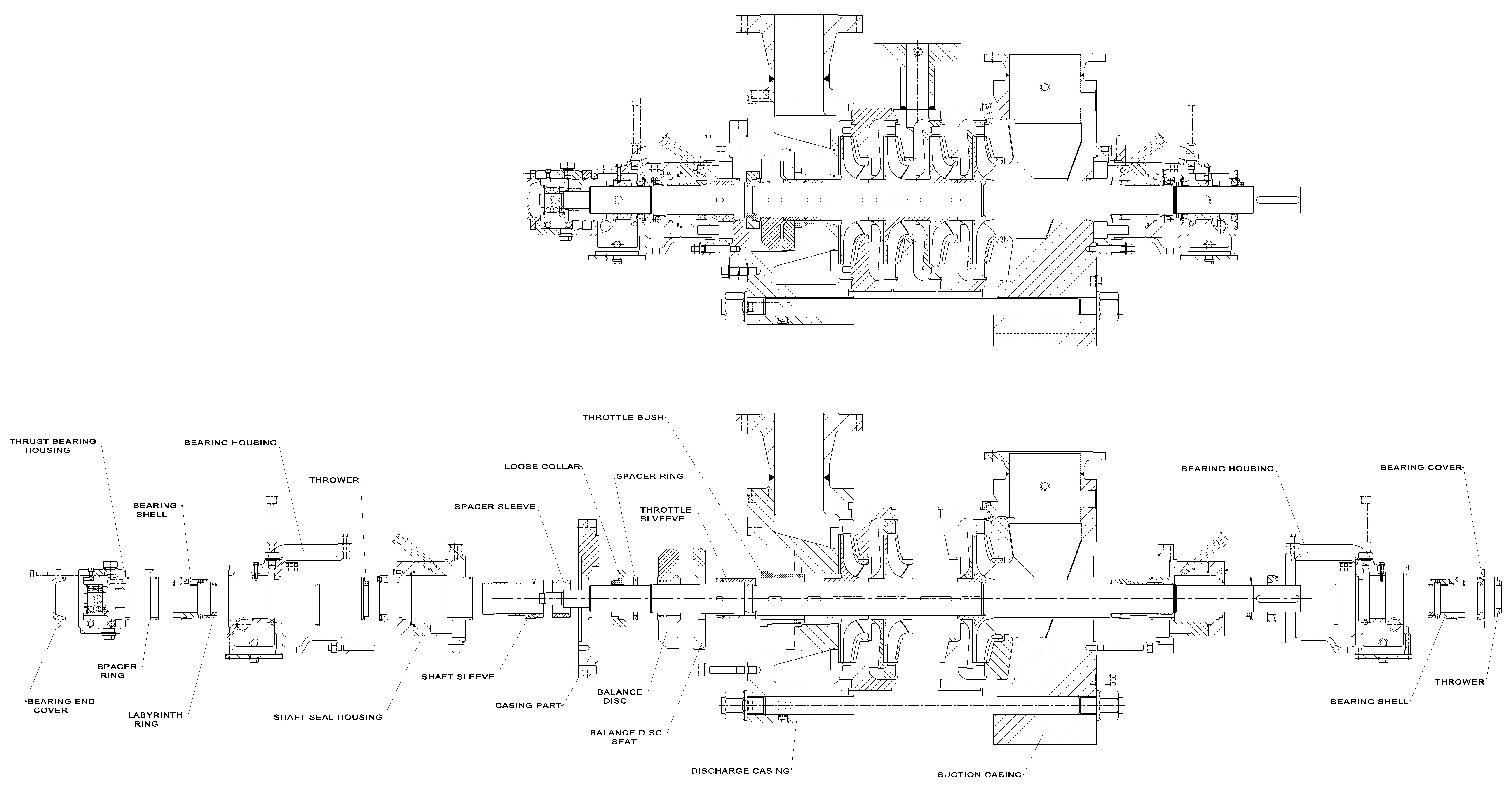
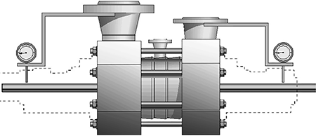
The following multistage boiler feed pump serves as an example (Image 6).
A pump health check is a partial disassembly of a pump to check key wear parts, including bearings, shaft seals, balancing devices and the internal wear ring clearance at the impellers (Image 6). The main casing is not disassembled, and it remains installed on the baseplate with the suction and discharge piping connected but isolated from the system. The pump health check is an inspection of the bearings, seal, balancing device and casing wear rings, as well as alignment verification.
Bearings inspection:
The first wear part to be removed in the disassembly are the bearings. Important checks for a sleeve bearing include examining the surface condition of the bearing babbitt. Wiping or adhesion is probably the most common problem for a pump sleeve bearing. Minor wear might be repaired at the site, but it is good to have a replacement bearing available to minimize pump downtime. There may also be side loading concentrations due to shaft misalignment with the driver.
Erosion and abrasion due to oil contamination is also possible. Collecting an oil sample and sending it for analysis is recommended. However, for the health check, the visual examination will tell users if they need to install a new bearing.
In addition to inspecting the bearing, be sure the oil supply and return connections are clean and not blocked by debris.
Seal inspection:
A shaft seal examination should be conducted following the bearings inspection. A visual inspection of the mechanical seal sliding ring faces is important. Seal faces with pitting or groves warrant replacement. Hard particulates can imbed in the softer ring material and score the surface of the hard ring material. Dry running causes adhesion wear. Proper air purging during commission is important to remove air from the seal cavity.
Cavitation wear may occur if the fluid of the seal cavity is too hot. For cavitation damage, users will find the pitting at the atmosphere side of the seal faces. Inspect the cooling or injection systems that keep the seals cool and/or clean.
These systems can sometimes foul or become obstructed and may need cleaning. Lastly, elastomers should always be replaced during a seal inspection.
Balancing device inspection:
The function of the balancing device is critical for a multistage pump. There are two key items that must be checked on a balancing device.
First, the surfaces of the parts that form the clearance between the rotating and stationary parts need to be checked. Light scoring is fine on the flat wearing surface of a balance disc, but deep scoring would necessitate its replacement. Second, the dimensions of the part at the wearing surfaces must be measured. A balancing device is a wear part; the dimensional check will indicate if it must be replaced.
Casing wear rings:
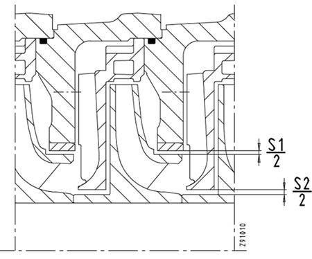
With the partial pump disassembly, users are able to inspect and replace, if needed, most of the important wear parts. However, there is still one important clearance that affects the efficiency, performance and reliability of the pump. That clearance is between the impeller eye and the casing wear ring (S1 in Image 7).
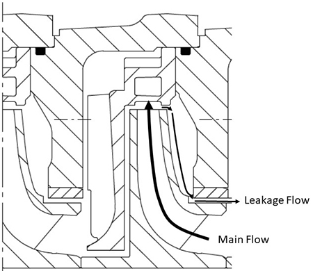
This clearance has two main functions. The first function is in regard to pump efficiency. This clearance separates the higher pressure discharge side of an impeller from the lower pressure suction side. If an impeller does not have the clearance S1, then there is recirculation flow back to the suction of the impeller, resulting in poor pump efficiency and performance (see Image 8).
The second function involves rotor support. This clearance with a pressure differential across it acts like a hydrostatic bearing. For multistage pumps, this can be particularly useful for supporting the rotor against hydraulic and gravitational forces. Known as the Lomakin effect, small increases in the S1 clearance reduce the stiffness of these bearings.
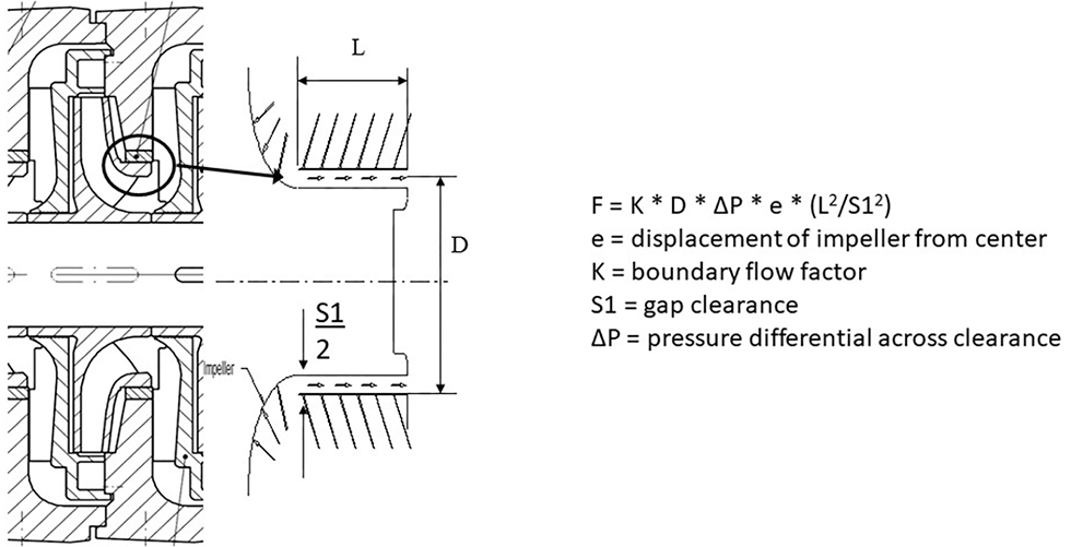
Knowing the value of S1 is important for the timing of the pump’s rebuild. Although this clearance is inside of the pump, there is a way to check it without disassembling the pump casing. An average indication of this clearance can be determined when the bearings, shaft seals and balancing device are removed. S1 is the next tightest clearance within the pump, and it can be measured with a simple rotor lift, as shown in Image 10.
Alignment verification:
Upon reassembly, the pump should be realigned with its driver. The radial bearings are removed for inspection, and when reinstalled, the rotor should be recentered. When this is done, realignment of the pump with its driver should be completed.
Unfortunately, a rotor lift check does not work for every multistage pump, but it works for a good percentage, and it is a great way to help monitor the condition of a pump and plan for its next overhaul.
The time needed for this process depends on the pump. On average, three to four days from the time pump disassembly begins is a good estimate. It is also important to plan ahead and have replacements for the parts being removed and inspected just in case they need to be replaced.
How often should a pump health check be performed? It depends on the operating conditions. If the pump is running in good to ideal conditions, then maybe every two to three years. Operating conditions less than ideal require more frequent inspections.
