What it is and methods for determining it.
Hydraulic Institute

What is NPSH3, and what are the methods for determining the NPSH3 of a rotodynamic submersible pump?

NPSH3 is the net positive suction head available to a pump under test at a constant rate of flow when the pump head is decreased by 3 percent as a result of cavitation caused by a decreasing available suction head. Sometimes NPSH3 is referred to as net positive suction head required (NPSHr). However, a pump’s NPSHr must be higher than the NPSH3 for the pump to operate without head reduction, and it may need to be higher than the NPSH3 for long-term reliable operation.

For more information on the required margins above NPSH3, refer to ANSI/HI 9.6.1 Rotodynamic Pumps Guideline for NPSH Margin.

The NPSH is established through the datum elevation of the impeller. The flow toward the pump must be uniform and free of undue disturbances. A pump tested with suction piping may require a flow-straightening device before entering the pump.

Arrangements for cooling or heating the liquid in the loop may be needed to maintain the required temperature.

Suction throttling NPSH test setup
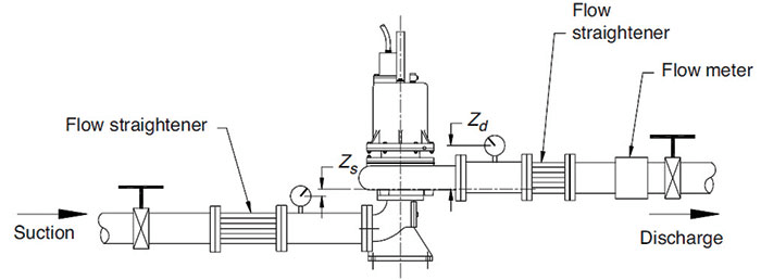
Image 1. Figure 11.6.7.2a. Suction throttling NPSH test setup

Multiple arrangements can be used to determine the NPSH3 characteristics of rotodynamic submersible pumps. One arrangement is shown in Image 1. The pump is supplied by a constant-level supply through a throttle valve followed by a section of pipe containing straightening vanes or a minimum of seven diameters of straight pipe to straighten flow.

This system arrangement decreases the turbulence produced by the throttle valve and makes possible a more accurate and reliable reading of suction pressure at the pump inlet.

This simple arrangement usually is satisfactory for NPSH greater than 3 meters (10 feet); however, the turbulence at the throttle valve tends to accelerate the release of dissolved air or gas from the liquid as the pressure on the liquid is reduced. A test made with this arrangement usually indicates higher NPSHr than what would be expected with deaerated liquid.

Variable-lift NPSH test setup
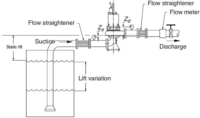
Image 2. Figure 11.6.7.2b. Variable-lift NPSH test setup

Image 2 shows a second option. The pump is supplied by a sump in which the liquid level can be varied to establish the desired NPSHr. Be careful to prevent entrained air or vortexing as the liquid level is varied. The priming connection should be installed above the eye of the impeller, either in the discharge pipe or on the pump.

For more on test methods for rotodynamic submersible pumps, refer to ANSI/HI 11.6 Rotodynamic Submersible Pumps for Hydraulic Performance, Hydrostatic Pressure, Mechanical, and Electrical Acceptance Tests.

Read more HI Pump FAQs by clicking here.

Issue