

Many high-energy multistage machines use thrust compensation devices to limit the amount of axial thrust a bearing must accommodate. The BB3-style machine (axially split pump) uses its opposed impeller construction to limit thrust, while a BB5 machine (radially split pump) uses a balance drum or disc arrangement to fix the issue. At the higher end of the pump energy spectrum, despite the use of thrust-limiting devices, there is a need to employ a sleeve tilting pad thrust bearing and lubrication system to handle the axial thrust.
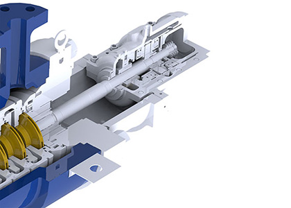 IMAGE 1: Typical sleeve tilting pad thrust bearing (Images courtesy of Hydro, Inc.)
The bearing construction consists of a sleeve bearing mounted inboard of the shaft-mounted thrust collar (Image 1). Thrust pads are arranged on either side of the thrust collar within the bearing housing to accept thrust in whichever direction is dictated by the design and the machine’s operating regime. Many pumps thrust outwards, loading the outer pads. There should always be a temperature difference between the loaded and unloaded pads.
When a thrust pad failure occurs, it can be difficult to diagnose the cause. The failure generally comes in the form of excess temperature. Understanding the bearing’s construction and how and why it accommodates thrust can aid diagnosis.
When diagnosing this type of failure, split the problem into two constituents:
Load: The thrust bearing is trying to deal with more load than it was designed for.
Lubrication: The thrust bearing lubrication is compromised—either the condition, amount or temperature.
With these constituents, heat is how the failure manifests, but the causes are different.
Lubrication issues can be tracked through the lubrication system and the cooling arrangements. Failure can also be due to oil contamination. I have witnessed poor maintenance practice that causes failure due to the lube-oil cooler being bypassed after a maintenance event.
Poor oil condition can be caused by a lube oil tank being too small. The short residence time caused the oil effectiveness to be compromised by entrained air. The pump owner had tried to cure a thrust overload problem by increasing the oil flow through the bearing system. This can be solved by understanding the way the bearing works.
Solution Process
To diagnose the thrust bearing problem, look at the direction of the thrust. If it has changed, this may be an indication of the operating conditions or pump condition. Also look at the level of the thrust versus time during startup. This points to longer standing design problems.
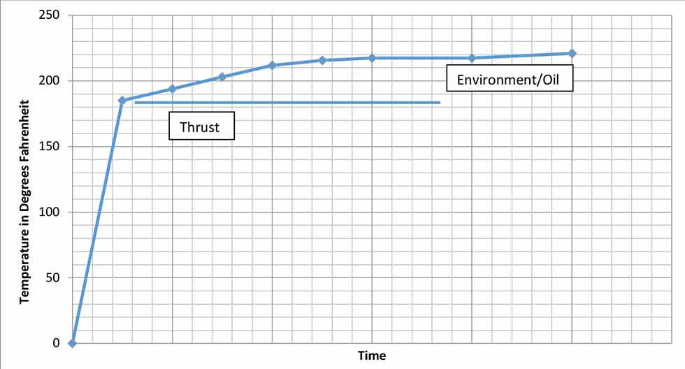
There is valuable information to be gained from the time versus temperature graph available from startup. The graph indicates the level of temperature associated with the thrust and is an indicator of the efficiency and condition of the balancing mechanism (Image 2). The effectiveness of the lubrication system at dissipating the heat follows the initial thrust condition. Notice on startup how the thrust comes quickly and the lubrication effectiveness comes into the equation later within the startup cycle.
Understanding this data is a proven way to focus diagnostic efforts when forensically examining any thrust pad failure.
