The first step of calculating the minor head loss is to determine the resistance coefficient (K) for the specific outlet from the tank. As published in the HI Data Tool, Image 1 provides K-factors for three different pipe inlets.
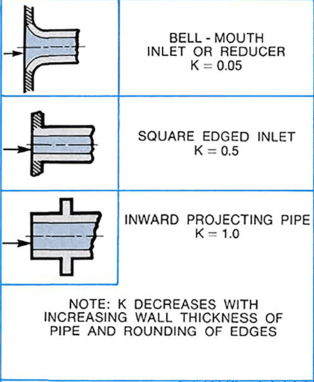
If there were multiple kinds of minor losses, they would be added together to calculate the total minor losses for the system. This calculation will be done for a single minor loss, specifically the bell-mouth inlet, the square-edged inlet and the inward-projecting pipe. These have K values of 0.05, 0.5 and 1.0 respectively.
For the three pipe entrances shown in Image 1 and a velocity of 8 ft/s (2.4 m/s), the head loss would be 0.05 ft (0.015 m), 0.5 ft (0.15 m) and 1 ft (0.3 m) respectively. This illustrates that the pipe inlet type has a major impact on the actual head loss, where the bell mouth has 5% of the head loss of the inward projecting pipe.
For additional information, reference the HI Data Tool at datatool.pumps.org.