Common Pumping Mistakes
by Jim Elsey
Summit Pump Inc.

In a hypothetical world, if the Department of Energy (DOE) showed up at your plant to conduct an energy audit of the pump systems, what grade would you receive? Do you get an A … or an F? Plant owners and managers are faced with balancing scores of urgent priorities every day—stock holders on one side demanding the plant run continuously to keep the profits high, and engineering (reliability) and maintenance on the opposite side screaming, “we need to shut down to fix the plant.”

Approximately 20 to 25 percent of the global electrical energy that goes to electrical motors is used to drive pumps. In recent years, you have likely noticed a major initiative in the industry to improve efficiency in pumps and their associated systems. This movement is led by the Hydraulic Institute and Pump Systems Matter, working in conjunction with the DOE to address energy consumed by all pumps currently in service and, of course, all future installations. The first part of the initiative’s proposal is to educate pump owners and operators on how to reduce energy requirements, then give them the tools to accomplish the task. In my personal opinion it is a herculean task, and I will also postulate that a reliable plant is most often an efficient plant and vice versa.

Centrifugal pumps on average have an efficiency of 65 percent, with a few studies pushing the number higher. I would also point out that the “average” pump, despite its capability to be of higher efficiency, is likely operating somewhere below 45 percent. Industry research at numerous facilities both in the U.S. and Europe shows that well over 50 percent of the pumps in a given plant are not operating at their most efficient point, and there are many units operating at efficiency points as low as 10 percent.

Efficiency Trade Offs

The pumps that are operated away from their best efficiency point (BEP), are worn out and have excessive clearances, or are simply the wrong pump for the application. Many pumps are not designed to be highly efficient on purpose, because they are designed for a specific service. For example, slurry, sewage and solids handling self-primer pumps are designed for reliability and long life at the expense of efficiency. Vortex, recessed impeller, disc and low flow-high head pumps are other examples of function over efficiency. Some pumps are assigned to an intermittent duty cycle when reliability and criticality supersedes efficiency. A pump that is required to run for five minutes once a week, ostensibly to lower a sump level, doesn’t need to be 75 percent efficient. It simply needs to operate reliably.

The most efficient pump I ever dealt with was rated at 91 percent efficiency. It was a large single-stage horizontal split case pump designed for more than 200,000 gallons per minute. I was the engineer responsible for the installation of six of these pumps during a cold winter in North Dakota. Typically, the wider the passages in a pump (higher flow rates) the more efficient the pump will be because there is substantially less fluid friction on the casing and impeller surfaces.

Most automobiles with gasoline engines are stretching to reach 20 percent thermal efficiency, though diesels are somewhat higher at close to 40 percent. I mention cars because they are something we can all relate to, and the public measures their efficiency in a different way than engineers who rate the thermal efficiency of the engine. The public measures car efficiency in miles per gallon. We can do the same with pumps if we look at gallons per minute (gpm) per kilowatt (kW) over some unit of time. That is, as a unit of work calculated from moving a unit of weight (fluid) over a unit of time.

A gallon of water weighs about 8.3 pounds, and we propose to lift it and several more gallons some distance or height during some period of time (minutes in this case). The basic power unit required to accomplish this task will be measured in kW (over time) since the majority of pumps are driven by electric motors. The term to describe this viewpoint is called “specific energy,” so we look for the unit volume delivered by the pump divided by the actual power consumed, or simply the gpm divided by kilowatt-hours (kW-h). Using this concept it is easier to see the efficiency of the entire pump system and not just the pump. This is important because the prevailing issue is not the efficiency of the pump itself. Most pumps are not operated in an efficient manner
due to how the system is designed or operated.

Water horsepower assumes 100 percent efficiency
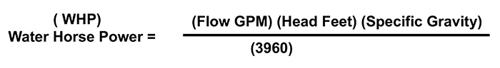
Figure 1. Water horsepower assumes 100 percent efficiency. (Courtesy of the author)

If a pump were 100 percent efficient, the formula for calculating the required power is laid out in Figure 1. We refer to this as the “water horsepower” (WHP), and it is a factor that serves engineers during the design phase of a project.

It would also be used as a factor in “wire to water” calculations. The more realistic formula/equation is Figure 2, where the factor of efficiency comes into play. Note that the flow, head and specific gravity are all in the numerator, which means they directly affect the horsepower required (think kWh). If you need more pressure or more flow, it requires more brake horsepower (BHP). If the specific gravity increases, the fluid now weighs more than water and so that, too, requires more BHP to accomplish the additional work.

Where pump efficiency is taken at the rated duty point and expressed as a decimal
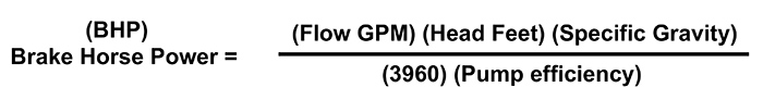
Figure 2. Where pump efficiency is taken at the rated duty point and expressed as a decimal

The pump efficiency is expressed as a decimal in the denominator of the equation (formula) so the effect of efficiency has an inverse result. Should the efficiency increase, the BHP will reduce and vice versa. From the formula you can determine the efficiency of a pump if you know the other factors.

This is not the method used by the original equipment manufacturer (OEM) on the performance test stand.

Background

An electrical induction motor converts electrical energy to rotational mechanical energy. The pump receives that mechanical energy and converts it to pressure energy, which manifests as flow and head. As a result of earlier industry requirements and a DOE government program, motors are more efficient than they were years ago. It is now standard for a new motor to be more than 90 percent efficient, sometimes approaching 96 percent. The motor maintains that high efficiency over the upper 50 percent of its horsepower operating range.

Pumps, on the other hand, only reach peak efficiency at one operating point or at the very least a small operating range. Pump operations that depart from the BEP will experience a marked drop in efficiency in addition to other deleterious effects such as radial thrust, cavitation and recirculation. Centrifugal pumps are really only designed for one condition point of head and flow. To operate anywhere else on the curve is simply a compromise. The key to an efficient installation is to design the system and properly select the pump so that it operates at its BEP most of the time. In reality, this rarely happens and is the main point of this article.

When a pump operates there are many types of losses that preclude the pump from being highly efficient. There are mechanical losses caused by bearings, packing or seals. There are volumetric losses due to recirculation, and there are hydraulic losses due to friction, some of which dissipate as heat and noise.

Additionally, there are losses due to sudden acceleration and deceleration of the fluid (shock losses). There are losses due to pump out vanes or balance holes on the impeller. There are losses due to running clearances in wear rings, throttle bushings and balance drums. Often overlooked, there are significant losses caused by turbulent flow created by vortices (eddy currents) that recirculate in front of an impeller and disturb the laminar flow required for the pump to operate as designed. Visualize that the angle of the incoming fluid flow should match the attack angle (leading edge) of the rotating impeller vane for efficient operation. These “upsetting vortices” are created by excessive impeller or ring clearances and are exacerbated by operating the pump away from BEP.

Just as you would not drive your car at 70 miles per hour in first gear or 55 miles per hour with the brake pedal fully depressed, you should not operate the pump with the discharge valve 50 percent shut or with the bypass or control valve fully ported back to suction, but this is happening every day in plants around the world, and the wasted energy can never be recovered.

Many pump operators do not have an accurate idea of where their pump is operating on the curve, and even more operators do not have a good grasp of their system curve dynamics or even the concept of a system curve. Simply stated, the pump will operate on its performance curve where the system curve dictates, that is where the two curves intersect. If you are not monitoring the differential pressure across the pump then you have limited knowledge of where the pump is operating on its curve, therefore you can’t know if the pump is being operated at its BEP.

A few methods exist to improve the efficiency of the pump itself and typically involve addressing the surface finish of the casing and impeller. As always, there are pros and cons to the methods.
Friction losses in a pump are directly proportional to the relative roughness (smoothness) of the casing, impeller and other waterway surfaces. One method is to apply superficial coatings that will yield varying results depending on the size of the pump and how well the surface was prepared and the coating applied. Note that the coating will also change clearances with the unintended consequence of reducing the expected benefit, especially on a smaller pump. The bigger the pump, the more benefit will be realized. Another method is to produce a highly polished finish (typically just on the impeller) to reduce fluid friction, which will offer good results but can also cause erosion and corrosion depending on the fluid.

More of a maintenance step than a design parameter are the pump clearances, which have a significant effect on the pump efficiency. Pump efficiency will decrease exponentially with increased clearances once the small range of initial design clearance is exceeded.

Last, but not least, investment castings or similar improved casting processes will yield smooth surfaces and also allow a few more feet of head development, which results in more efficient pumps by a few points. There are other methods, but most will yield results that do not offer sufficient payback for the expense incurred or are unique to a certain pump
or system.

Summary

Again, the overarching issue is more likely the system than the pump. The Hydraulic Institute and Pump Systems Matter offer great resources to assist in evaluating your pump and associated systems to first assess and determine the current efficiency and then to take steps to affect positive change. The desired outcome is to have the right pump of the right size and materials that is operated and maintained correctly.

A good example is the water pump in your car, which is designed for that specific application. Automotive water pumps are variable speed with a pump-friendly fluid on a closed system. The pump curve is expertly matched to the system curve so you can operate the pump for a long time with only minimal issues.

References
Optimizing Pumping Systems; Pump Systems Matter and Hydraulic Institute

To read other articles in the 'Common Pumping Mistakes' column, go here.