

I find it amazing how many people still use Excel spreadsheets to solve engineering calculations. Don’t get me wrong, I still use Excel in place of a calculator to perform quick and dirty calculations, or to present calculated results in table form. Excel is an easy-to-use spreadsheet program with a host of functions, but the applications developed must be clearly defined, well documented and supported.
Most engineering spreadsheets are typically created by a primary user. As time goes on, the user adds new features and functionality to make their life easier. At some point, others are interested in using the homegrown spreadsheet and ask the developer for a copy. Once this happens, it is no longer a spreadsheet, and it becomes an application.
Many of the people using the application were not involved in the development. Instead, they use it to perform a defined task, usually with financial implications. Now, the new user has to learn how the application works, what its limitations are and whether the results make sense. Often, many users will make their own modifications, thus introducing design control issues.
Most engineering calculations have to be reviewed and approved by others. When these calculations are done with a spreadsheet, the reviewer must have access to the spreadsheet. This increases the workload of the checker/reviewer.
Enter CMS Applications
Many engineering calculation tasks have evolved into computer modeling and simulation (CMS) applications. These professional grade applications have been developed to perform detailed modeling and simulation calculations used to design, build, operate and maintain engineering processes. Many of these CMS applications are a key element of the new digital twin technology that I have written about in past Pumps & Systems articles.
Instead of performing a single engineering calculation where the input data is entered and the results are displayed on the spreadsheet, the CMS incorporates the workflow needed to accurately perform the calculations. In this article, I will demonstrate a typical CMS application functionally found in many of the commercially developed applications for pump and piping systems by looking at how to size a pipeline in a CMS application.
The first step is inserting the pipeline on a flow diagram. That is done by connecting the individual pipelines to the installed equipment. Once this is done, the pipeline is named using the project’s naming convention. Using the drawing format, everyone knows where the pipe is in the system and the equipment connections.
Most piping projects incorporate design control. Many CMS applications often incorporate pipe specification with pipe classes to maintain the project design controls.
Using this approach, the user selects the proper pipe class from the pipe specification. The proper pipe table and schedule is used to display the available pipe sizes. The pipe classes also provide the list of approved valves and fittings for all the pipelines.
Selecting accurate process fluid properties has a major effect on pipe sizing and head loss calculations. Most CMS applications use fluid tables to look up the necessary fluid properties. By selecting the appropriate fluid table from a list and entering the process fluid temperature, all the data needed is automatically entered.
Selecting a reasonable fluid velocity is the primary criteria for pipe sizing. For example, the pipe specification may use 6 feet per second as the sizing velocity. By entering the design flow rate for the pipeline, the application uses the appropriate pipe table and schedule, and it then calculates the recommended pipe diameter from the available nominal sizes found in the pipe class. This streamlines the data entry while maintaining control of the design.
The use of the pipe class also limits the selection of the allowable valve and fitting types for selection by the user. The final item needed for pipe design is the pipe length. Once that is entered, the application selects the pipe diameter and calculates the pipeline head loss.
Ease of Use & Total Picture
Programs like Excel have many features like copy, paste and group edit that streamline the creation of involved spreadsheets. Most CMS applications also incorporate these features making it easier to create large piping systems.
Much of the system data in piping applications depend on the manufacturer’s supplied data for the installed equipment. Proper representation of equipment has a major impact on system operation, and many of the CMS applications use vendor supplied data to improve the system accuracy. A few CMS fluid applications can import pump and control valve data supplied directly by the manufacturers, which increases the accuracy of the model.
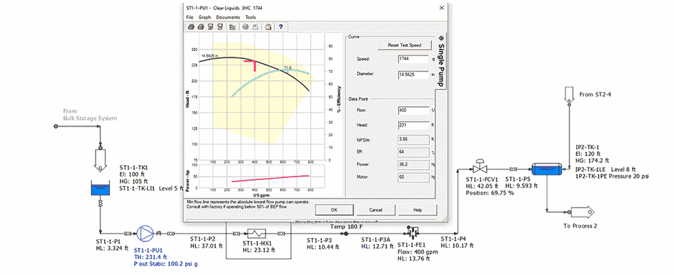
Once the as-built system design data and the as-operated boundary conditions have been entered, the system model can be used to simulate the operation of the total system. The fluid applications calculate the balanced flow rates and pressures, providing a clear picture of system operation. Image 1 is typical of the piping and instrumentation design (P&ID) interface used by many CMS piping applications.
Piping systems are expensive to design, build, operate and maintain. They are made of many interrelated parts that must all work together efficiently to meet the economic objectives of the facility.
The advantages of using a dedicated CMS application for piping systems far outweigh any savings that can be achieved in creating a host of homegrown Excel applications; it would be similar to your accounting department tracking all payables and receivables on an Excel spreadsheet.
To read more Pump System Improvement columns, click here.
