
Specialized centrifugal pumps handle liquids with up to 70 percent gases.
05/13/2015
Air and gas entrainment in pumped liquids is a long-standing problem for centrifugal pumps. A conventional method of dealing with this issue is using recessed, impeller-style pumps. However, this technology is highly inefficient. Other methods use expensive and environmentally unfriendly defoaming chemicals. Some facilities use too much defoaming chemical to prevent pumps from vapor locking or to halt flow instabilities. Many operators have problematic pumps that continue to vapor lock. This is a result of too much air entrainment in the process.
Unconventional Solution
One particular centrifugal pump moves liquids containing large amounts of air and other gases. The system can pump liquids containing up to 70 percent gases. In conventional centrifugal pumping, a liquid's air or gas migrates to the impeller's center. This is because the centrifugal effect imparted by the impeller vanes onto the liquid causes the air or gas to separate from the liquid. The impeller center is an area of low pressure, which leads to gas accumulation. Eventually, the gases increase so much that a bubble forms, preventing the liquid from entering the impeller. The pump essentially vapor locks and no longer performs. One specially made impeller features teardrop-shaped balancing holes located closer to the center of the impeller, where the gases accumulate. The balancing holes allow gases to pass through the impeller eye. By introducing a lower pressure behind the impeller, the balancing holes allow a removal route for the gases accumulating in the impeller's eye. This concept allows the pump to perform like a normal centrifugal pump while pumping liquids with high gas entrainment. Two different pump models use this design, but each employs a different method to create the lower pressure behind the impeller.Pump Designs
The first pump design has an external liquid ring vacuum pump mounted next to it. This model has a unique stuffing box arrangement consisting primarily of an expeller inside the stuffing box located behind the impeller, a degas pipe and a recirculation pipe. The vacuum hose from the external vacuum pump connects to the centrifugal pump's degas pipe, which is attached to the stuffing box (see Figure 1). This creates lower pressure behind the impeller, inducing gases to migrate through the balancing holes and into the degas zone, which is the stuffing box area in conventional pumps.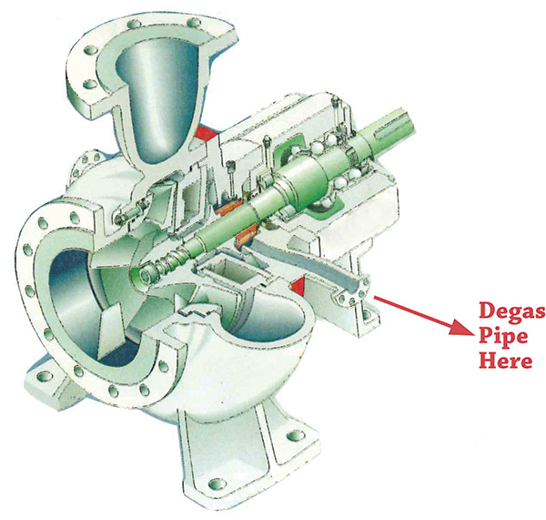 Figure 1. An external vacuum pump is attached to the centrifugal pump. (Images and graphics courtesy of Fluid Process Equipment
Comparing Pump Models
The second centrifugal pump model uses the same volute and impeller as the first, but the stuffing box chamber is different. The second model uses a degas rotor instead of an expeller (see Image 1). The degas rotor is similar to the rotor used in a vacuum pump. In fact, the pumps incorporate a miniature vacuum pump inside the stuffing box behind the impeller.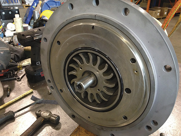 Image 1. Degassing rotor found inside internal degassing pump type 2