

Designing a new pump from scratch is not easy, and there is nothing on the market that will provide all the necessary tools to design a pump exactly the way it has been requested. Some of these sources may provide insight on the impeller design, while others may help with the layout of the hydraulic passages (casing/bowl, volute, diffuser, crossover, etc.).
However, it is the combination of the two hydraulic components working collectively that will determine the performance characteristics of the pump. For instance, if the impeller eye design is restricting the pump’s runout capacity, increasing the flow areas within the volute may have no effect on the runout performance. With the lack of standardization on pump hydraulic design, and with no two companies or engineers using the exact same methods, sources or techniques, this article will focus on industry accepted considerations when designing pumps for potable water applications.
Most pumps used in potable water applications are of the rotodynamic type, more specifically, of radial (or centrifugal) design. This is not to say mixed or axial flow pumps cannot be used in potable water applications, just that overhung horizontal end-suction, overhung vertical in-line, horizontal split-case and vertical turbine (discharge through column) pumps are traditionally used in the transfer of potable water. Potable water centrifugal pumps are specifically designed to circulate or move clean, fresh drinking water from one location to another.
These pumps are used in a variety of settings, such as municipal water systems, water treatment plants and agricultural irrigation systems, and their design should meet all relevant regulations, standards and local codes. In the design process, there are important considerations to address, ranging from the materials of construction to the type of mechanical seal and appropriate piping plan. This article focuses on the important considerations for volute casing type pumps, but depending on the application or environment, there may be additional factors that affect the design of the pump.
Pump Design
The hydraulic design of impellers, volutes and casings is not standardized within the pump industry and will not be covered. However, there are several factors that are universally accepted that aid in the hydraulic design of potable water pumps, and their value should be known to everyone from design engineers to end users.
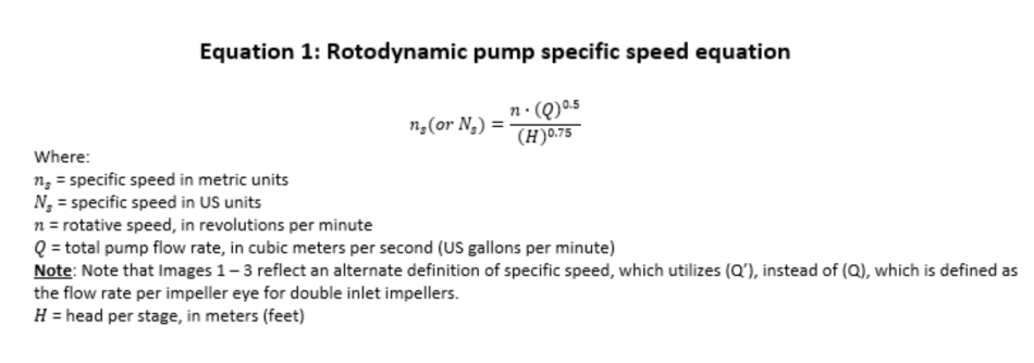
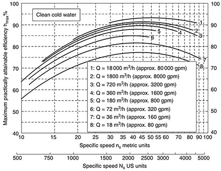
When designing a potable water pump, efficiency is an essential parameter that needs to be considered. It is affected by various factors such as pump type, size, orientation and operating speed. One important factor that affects pump efficiency is the specific speed of the pump. Specific speed (Ns) is a parameter used to describe the performance of a rotodynamic pump. It is defined as an index of pump performance at the pump’s best efficiency point (BEP) rate of flow and head, with the maximum diameter impeller, and at a given rotative speed (Equation 1).
The index informs the design engineer of the type of pump required for the application. Along with the pump type, the specific speed will establish the maximum attainable efficiency achievable for the particular design. The attainable efficiency of a pump is the maximum efficiency that can be achieved for a given pump design based on pump type, design (BEP) flow rate and the specific speed (Image 1).
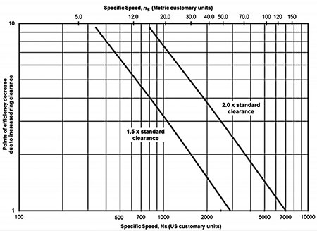
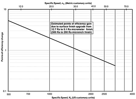
There are additional factors that can affect the attainable efficiency, such as surface finish of flow passages and the running (wear ring) clearances of the pump’s internal components; however, their effect on maximum attainable efficiency is dependent on the specific speed of the pump (Images 2 and 3). Higher output capacity pumps at BEP typically have a greater attainable efficiency than lower capacity pumps when designed for similar specific speeds, and understanding this relationship is crucial in the design process.
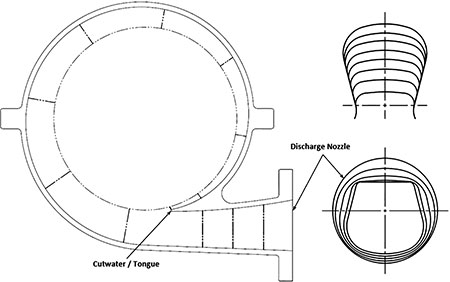
The flow area transitions created during the suction (inlet) and volute development stage of design can also affect pump efficiency. These transitions need to be designed to minimize losses, and this can be done by minimizing sudden changes in cross-sectional areas and smoothening the transition from the suction nozzle
to the impeller eye section, as well as from the volute cutwater (or tongue) to the discharge nozzle. This is typically done by evaluating both the suction and discharge passages separately and fine tuning the area progression in the direction of the flow. Image 4 shows the typical gradual expansion of cross-sectional areas in the volute development from the cutwater (or tongue) to the discharge nozzle for a horizontal split-case (BB1) pump.
Additional considerations in the pump design that have not been covered consist of axial and radial thrust, bearing life, shaft deflection and stress, casing wall thickness, number of casing bolts and the area between the impeller vanes versus the total impeller eye area.
See American National Standards Institute (ANSI)/Hydraulic Institute (HI) 14.3-2019 Rotodynamic Pumps for Design and Application and HI 20.3-2020 Rotodynamic Pump Efficiency Prediction for additional information.
Construction Materials
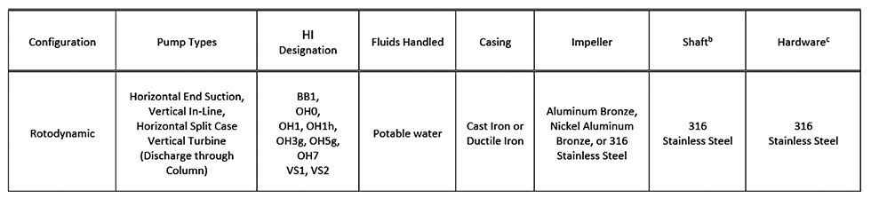
Another critical consideration when designing a potable water pump is the selection of materials of the wetted parts (components in direct contact with the potable water). The materials used in the construction of the pump should meet all relevant regulations and standards, such as NSF/ANSI 61 or FDA standards and must not contaminate the water supply. Stainless steel, bronze and various plastics are common materials used in the construction of potable water pumps. Image 5, which is a modified version outlined in Appendix B of the Hydraulic Institute Pump Application Guideline Water Treatment Plant Pumps, shows typical materials of construction that are in compliance with regulations and standards.
Mechanical Seals, Compression Packing & Flush Plans
The selection of the right mechanical seal is another critical consideration when designing a potable water pump. The mechanical seal must meet certain requirements to ensure it is safe and suitable for use with drinking water and be designed to prevent leakage from the pump. It must also be able to prevent any contaminants from entering. There are several types of mechanical seal designs that may need to be used to meet the specific application requirements, but most commonly, single mechanical seals are used in potable water applications.
The specific design of the mechanical seal used will vary depending on application requirements. Acceptable materials for the seal face, seal balance, integrated metal components and secondary seals all need to be considered and are outlined in the Hydraulic Institute Pump Applications Guideline for Mechanical Seals for Pumps. However, with an increased regulatory focus on per- and polyfluoroalkyl substances (PFAS), in the future, pump designers may need to consider alternate materials for gaskets, O-rings, shaft seals and packing.
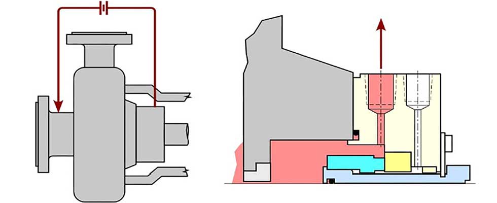
There are several different types of mechanical seal piping plans used in potable water applications, including Plans 2, 11 and 13 (Image 6). Plan 2 is a dead-ended seal chamber with no flush fluid circulation. A Plan 11 involves product recirculation from the pump discharge to the seal through a flow control orifice or valve, and a Plan 13 involves product recirculation from the seal chamber back to the pump suction. The selection of a seal piping plan will depend on the specific requirements of the application, including the operating conditions, environment and any regulatory requirements.
Another shaft sealing method that is commonly used in potable water applications is compression packing. When selecting seal packing materials for potable water applications, it is important to choose materials that comply with relevant industry standards and regulations. Common materials used for seal packing in potable water applications include braided polytetrafluoroethylene (PTFE) synthetic yarn, braided expanded PTFE or graphite. However, consult with the supplier for materials that meet all relevant regulations and standards.
Ease of Maintenance & Reliability
How easily a pump can be assessed during standard maintenance is an essential consideration when designing any type of pump, but is especially important in pumps responsible for delivering safe drinking water to households, businesses and public facilities. Any failure or malfunction to the pump can have serious consequences to public health and safety. By prioritizing ease of maintenance in the design, engineers can ensure easy access to critical components that may need to be replaced or serviced over time. This includes impellers, bearings, seals and other parts that may wear out or degrade during operation.
In terms of reliability, choosing materials that are durable and resistant to corrosion, and that meet all relevant regulations and standards, is essential. Proper design of the pump to meet the needs of the application is also crucial, as an undersized or oversized pump can result in accelerated wear, a higher risk of failure and a reduction in energy efficiency.
Designing a potable water pump requires careful consideration of several important factors, ranging from the hydraulic design, materials of construction, mechanical seal and its appropriate piping plan to ease of maintenance and reliability. By taking these considerations into account, designers can ensure the pump will be effective, efficient and safe for use in a wide range of potable water applications.
