

Bolted connections under cyclic loading are prone to self-loosening. Once preload is lost, the risk of failure in the connection is increased. To prevent failures due to self-loosening, it is helpful to understand the mechanism of self-loosening.
Most bolted joints consist of at least two joint components along with the fastening system. The fastening system may be a bolt and a nut, a bolt or screw and a threaded or tapped joint component, the bolt and nut with a variety of washer designs, etc. In the most basic form, a joint consisting of two plates along with a nut and bolt is shown in Image 2.
.jpg)
The bolts are preloaded to a force in the bolt (Fb). The amount of stretch in the bolt is proportional to the stiffness of the bolt and the active length (L).
The equation for bolt stretch is shown in Equation 1:
dL = (Fb L)/AE
The precise equation is not critical for this discussion. However, it is important to note that the stretch is proportional to the preload and bolt length. If bolt length is fixed and the load is constant (and hence, the stretch), then this is a static application.
In 1969, Junker6 indicated that transverse loading (perpendicular to the bolt’s axis) is most likely to result in self-loosening. Since that time, many studies have confirmed that cyclic transverse loadings result in a similar pattern of events that lead to the unloading of a prestressed bolt. Image 1 shows relative slip (a) between the joint members during each cycle of vibration.
As this slip occurs, it is plain to see that the load on the bolt will also change. This is revealed in Junker’s test data where there is an oscillation in load during each vibration. This variation in preload will be proportional to the amount of relative transverse displacement and the stiffness of the bolt. If the bolt preload changes during each cycle (dF’b), then the bolt stretch must also change by a proportional amount (dL’). The equation for the change in force during each cycle can be solved in Equation 2.
dF’b = (dL’ AE)/L
Taking this to extremes, if the value for a or bolt stiffness is large, then the change in force would be greater. Conversely, as these values approach zero, there would be no expected change in preload. In addition, if the bolt length was longer, then the change in force would be smaller for each cycle. This is because longer bolts add more elasticity to the fastening system. To an even greater extreme, if the bolt was infinitely long, there would be no change in load during each cycle. This would become a static application. In general, the loss of preload due to vibration follows a similar general pattern and occurs in two observed stages. Stage I shows a gradual relaxation from the initial preload. Once the load drops below some critical value, Stage II begins, and there is a rapid loosening.
There is a relationship to the angular rotation of the fastener components with respect to the joint and that value is ϴ, shown in Image 3.
.jpg)
IMAGE 3: Relationship of angular rotation of fastener components
This makes sense intuitively. If the nut backs off (rotated), then one would expect the load to drop quickly. Many products that aim to prevent bolt self-loosening failures aim to reduce or eliminate the losses in Stage II of the curve. These products include ways to reduce or counter the rotation of the nut or bolt head with respect to the joint. Each of these has its own pros and cons with respect to preventing the rotation of components. Some examples are mechanically locked fastening systems like lock wire or pins, thread locking compounds, elastic stop nuts or bolts with nylon patch material, modified thread systems, serrated washer systems and lock or toothed washers. Rather than reduce the load loss in Stage II, it would be better to reduce the load lost in Stage I so that Stage II never occurs. There is little to no angular rotation in Stage I. Most attribute the loss of preload in this stage to the embedment of plastic deformation of the stressed components during each cycle of load. Assuming that this is true, then it is also reasonable to assume that the rate of embedment diminishes over cycles.
The curve agrees with this assumption given that the load lost after some early losses flatten out to a comparably lower rate. Based on the equation for the change in preload discussed earlier, if the bolt length was long, this would increase the system’s elasticity and the change in preload due to any embedment would be reduced proportionally. Another way to increase the elasticity of a bolting system is to use Belleville springs. Bellevilles can increase a bolt’s effective length by a factor of 10X or more.
Now, consider a case where one Belleville is added to the fastening system and the added elasticity (deflection) of the spring is .015 inch (Image 4).
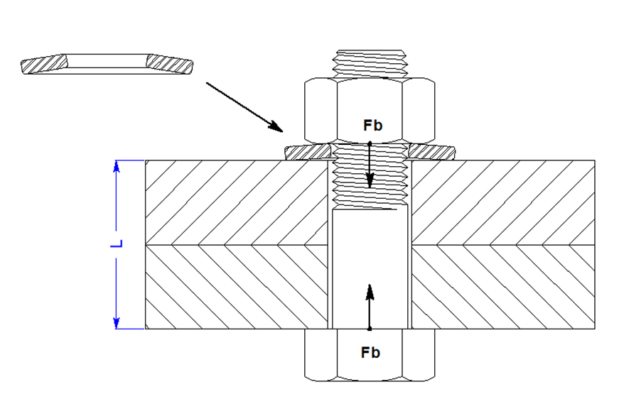
IMAGE 4: Impact with Belleville added to system
With the same assembly, assumed grip length and vibration displacement, the change in load is reduced by a factor of 11 (since bolt stretch is not lost). The load change during each vibration is ±91 pound force (lbf). This is virtually a static application since the change in force is slight. This should reduce the embedment at least to some degree. Even if the same embedment occurred, the loss of load would also be 1/11th of the system with no Belleville. As a result, the load would only fall to 5940 lbf.
It should be noted that friction should not be ignored. If friction in the bolting system approached zero, then no bolted joint would maintain preload. Load could be applied to the bolt using torque but as soon as the wrench was removed, the nut would immediately unload because the friction is the only thing that keeps it in place. There are many studies that confirm that vibration increases this tendency and so friction should be a consideration for the design of any bolted system. At a minimum, understand that reducing friction through lubrication, etc., may not improve retained preload in a system subject to unloading due to vibration.
Increasing the elasticity on a bolted system subject to vibration should reduce the tendency of the system to unload for two reasons: the change in force during each cycle of vibration is less or the loss of load due to embedment will be reduced. There are several methods to increase the fastening system elasticity including using longer bolts, bolts with reduced diameter and employing Belleville springs.
References
Bickford, John H. Introduction to the design and behavior of bolted joints: non-gasketed joints. CRC press, 2007.
ÇAVDAR, K., 2015. Self-Loosening Problems of Preloaded Bolted Joints. Uludağ University Journal of The Faculty of Engineering, 20(1), p.103.
Fatigue Resistant Bolts | Engineering Library. (n.d.). engineeringlibrary.org. Retrieved January 7, 2022, from engineeringlibrary.org/reference/fatigue-resistant-bolts-nasa-fastener-design-manual
Friede R. and Lange J. (2009) Self loosening of prestressed bolts, Nordic Steel Construction Conference NSCC2009, Malmö, 2-4 Sept. 2009, 272-279.
Jelaska, D. Fatigue safety factor general formula proposition for the prestressed components subjected to arbitrary CA stress cycling process.
Junker, G.H., “New criteria for self-loosening of fasteners under vibration,” Aircraft Engineering & Aerospace, vol. 44, no. 10, pp. 14–16, 1969.View at: Publisher Site | Google Scholar
Rasmussen, C. (2021, June 22). Why preload in bolts is important for fastener success. Mentored Engineer. Retrieved January 7, 2022, from mentoredengineer.com/why-preload-in-bolts-is-important-for-fastener-success
Shigley, J.E., Mechanical Engineering Design, 3rd Ed., McGraw-Hill, New York, 1977.
