“Instrumentation in Pump Systems 101” highlighted that instrumentation serves as the “eyes and ears” of the pump, giving users the confidence that their system operates correctly through basic measurement devices like switches, gauges and transmitters. This follow-up article will go beyond the foundational elements and focus on advanced strategies, including optimal instrumentation placement considerations, maintenance (calibration and verification), troubleshooting and modern instrumentation technologies. The advanced practices are essential for maximizing instruments’ longevity, dramatically reducing costly downtime and improving the overall reliability in industrial pump systems.
Instrumentation Placement & Installation Considerations
Sensor placement is critical for ensuring that instruments provide accurate and useful data. Poor installation can lead to inaccurate readings, false trips or alarms and wasted maintenance efforts. For pressure instruments, it is ideal to install them away from turbulence or vibrations caused by valves and control elements. This will allow users to retrieve stable and representative readings. Isolation valves and pressure dampeners allow for easy maintenance without process shutdown.
For temperature instruments, it is best to mount in zones that provide a true reading of the condition, such as the bearing surface or a sufficient insertion depth into the media. Ignoring these details results in data that may not reflect true pump health, leading to incorrect decisions.
Maintenance: Calibration & Verification
Understanding the differences between calibration and verification is key to proper maintenance. Calibration is the process of comparing an instrument’s readings and outputs to a standard known parameter and adjusting the device to eliminate errors. Verification is checking the device’s health and accuracy without making adjustments. Both are equally important to ensure precision process measurement. The intervals of maintenance may vary, but critical pressure, temperature and smart devices should be verified every six to 12 months, or according to manufacturers’ standards. One of the top challenges facing instrumentation maintenance teams is the amount of time required for instrument calibration, making maintenance activities labor-intensive and inefficient.
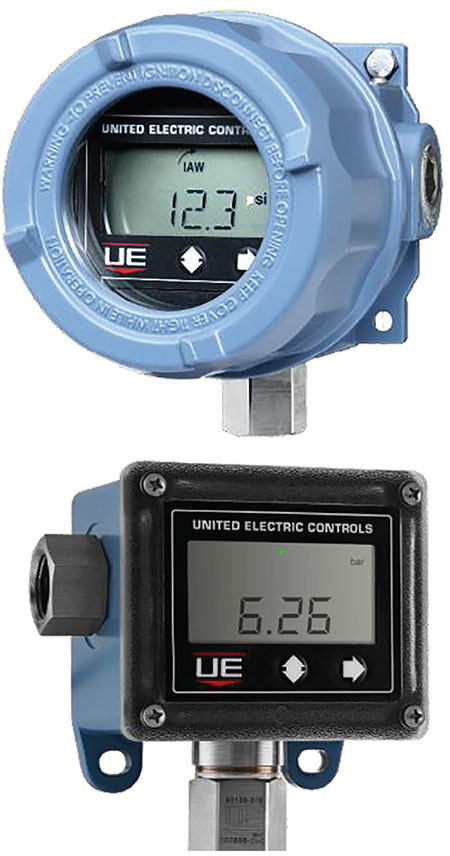
There are instruments in the market today that allow for on-site calibration and verification via the programming interface of the display. This means the maintenance team no longer needs to uninstall the device and bring it back to the instrument shop to calibrate and reinstall the device. Such a solution solves an industry-wide problem and saves up to 50% maintenance time for the operator.
Troubleshooting Using Instrumentation Data
Analyzing trends across instruments and devices is the most effective way to identify common pump issues and improve accuracy. For example, when data shows a steady drop in outlet pressure, this suggests the rotor is badly worn. An increasing motor temperature indicates too much friction in the bearings or motor overload. In addition, irregular flow readings suggest problems such as cavitation or pressure fluctuation in the line.
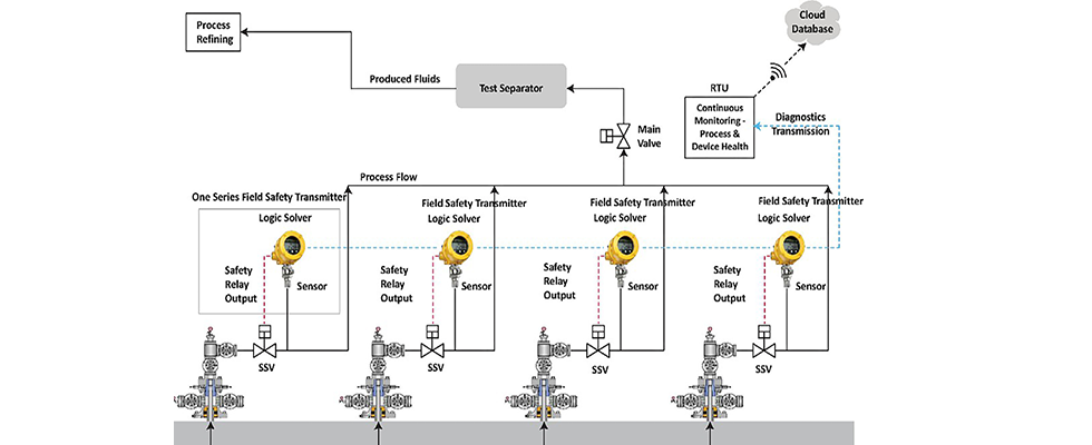
Some instrumentation even has advanced features such as “plugged port,” which can help the pump operator detect if the process port is clogged with media. The following is a case study where the plugged port feature on a pressure instrument installed on a safety shutdown valve helped a major oil and gas producer increase production uptime in a remote oil field.
Case Study
Challenge
Four wellheads feed medium American Petroleum Institute (API) crude oil to a separator. During extraction, paraffins could coagulate, especially during colder months. This would cause blockages in the individual wellhead’s hydraulic pressure measurement and safety shutdown system, leading to inaccurate pressure measurements and nonclosure of the individual wellhead’s safety shutdown valve (SSV). If this abnormal condition were detected at the test separator, the main valve accepting flow from the four wellheads supplying it would fail-safe and shut down the entire process, even if other wellheads were operating as designed. Consequently, this would result in process downtime and even potential risk for equipment damage. Labor-intensive inspection of the wellheads to determine the problematic one would be required.
Solution
Pressure instrumentation with the plugged port feature enabled was installed on each wellhead. The feature allowed operators to set time and percent of change values for the process, which would indicate a deviation from normal operating conditions. If pressure flow were restricted due to blockage, the instrument would initiate a direct, fail-safe shutdown of that wellhead, while the others continued to function.
Operators were remotely alerted to the event when the safety relay failed to open, and the 4-20 milliamps (mA) output dropped to 3.6 mA, indicating a fault (per User Association of Automation Technology in Process Industries [NAMUR] standards). Locally, the phrase “plugged port” scrolled across the digital display. By utilizing a standalone system per wellhead, the problematic one was easily identified so maintenance turnaround time and downtime were greatly improved. Blocked flow lines were confined to the problematic wellhead rather than the entire process. Additionally, reduced system design complexity was realized without changing the host system.
Smart Sensors & Digital Integration
The next generation of pump monitoring is shifting toward wireless industrial monitoring. This shift removes the physical and financial limitations of traditional wired infrastructure. Using communication protocols like WirelessHART, facilities can now deploy a network of instant “smart” monitoring points, even in hard-to-access locations. With 24/7 continuous and pervasive monitoring of pressure and temperature variables in a pump system, this enables operators to adopt a predictive maintenance strategy that identifies a problem before catastrophic equipment failure occurs.
Smart instrumentation is fundamentally transforming reactive devices into proactive, self-monitoring systems. Implementing efficient installation practices, maintaining a strict calibration schedule and using smart features of the digital integrated sensor technologies allows industrial facilities to improve their operational uptime. Current pump operators are strongly encouraged to evaluate their pump installations and identify immediate instrumentation upgrade opportunities to benefit the reduction in maintenance cost and time. The next evolution may focus on using this integrated smart instrumentation and its data for energy efficiency models.