To optimize system operation, designers must match the conditions that encompass the system curve.
by Jerry Ruc

Process and maintenance engineerImage 1. Process and maintenance engineers should review the pumping system design in the event of a process change. (Image and graphic courtesy of Sulzer)

Many pumps in operation today were built in the 1960s and ’70s, which is a testament to the original design and the skill of matching the pump to the operating demands of the application. A properly specified pump will operate reliably for decades, requiring few repairs. Still, pumping applications account for more than 20 percent of global electric motor energy consumption, so conscientious plant owners strive to maximize the efficiency of this equipment. The older the equipment, the more difficult the task becomes.

To optimize system operation—even those consisting of older pumps—designers must match the conditions that encompass the entire system, typically referred to as the system curve. The system curve represents the loss of energy in the system with a variation in flow rate. It is affected by a number of factors including frictional losses due to pipe diameters, surface roughness of the pipes and static losses, such as changes in pressure or elevation. The pump duty point (design point) is at the intersection of the pump characteristic curve and the system curve.

As operating conditions evolve over time, pumping application demands also change. These changes can be seen in flow, media characteristics or duty. However, just because a pump is capable of operating on the outer edges of the system curve does not mean performance or reliability will not be negatively affected.

For this reason, manufacturers establish the minimum operating flow as well as all of the limiting design conditions, including net positive suction head required (NPSHR) and maximum flow. Operators must understand the consequences of dialing back pump flows, which means measuring the operating conditions and calculating the point at which the pump will operate on the system curve.

Failure at Shutoff Flow

This concept can be illustrated by a recent repair project. A multistage boiler feed pump was brought to a service center for repair, and it was immediately clear that the pump had suffered severe damage. An initial inspection showed that the suction-side seal, several impellers, sleeves and stationary components had been destroyed. The evidence indicated that the pump had operated at or near shutoff flow.

When a pump operates in a boiler feed system, iron oxide deposits are often found in the casing. In this example, the deposits were absent in the first three stages of the pump but intact on the latter stages. This indicated that the pump had experienced a condition where the input energy from the impellers had turned the water to steam before it had a chance to exit the pump. The presence of steam in a pump is a violent condition that induces vibrations and can lead to surface erosion.

Normally, the frictional losses in a pump are converted to a few degrees of heat and discharged in the water flow. With very low or no flow, this energy builds in the pump. Eventually, the heat input to the liquid builds to an amount that surpasses its vapor pressure and it becomes two phases—liquid and gas. As the input of energy increases, the liquid heats to the point of transformation and turns completely into the gas phase.

Operating a pump under these circumstances is inefficient, and operators should take steps to properly assess the minimum flow requirements of an installation and perform remedial work to indicate when this condition is not being met.

Causes of Failure

The possible causes of the pump failure were reviewed with the plant owner who was keen to avoid similar cases. A number of issues were highlighted, including a misunderstanding of the required flow rate of the pump. The plant bases calculations mainly on steam rates, so these were converted to water flows and plotted on the pump operating curve. This established that the pump was operating close to the minimum flow point and that its pump operating curve was fairly flat at the lower flow region.

consequences of dialing back pump flows
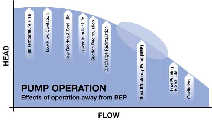
Figure 1. It is important to understand the consequences of dialing back pump flows and the effects on reliability.

To make matters worse, the failed pump discharges into a header, along with other similar pumps. This setup creates a parallel pumping system that is designed to increase system flow. The balancing act of a parallel operating system is to ensure that each pump is operating equally in terms of flow. The main control valve will provide the necessary backpressure to locate the pumps on their curves, but this is based on the assumption of equal conditions at the suction point. A centrifugal pump is a differential pressure device, meaning lower suction will deliver lower discharge pressure, which will position the pump on a slightly different point on its curve.

The pumps automatically adjust their flow output to match the backpressure within the system. Pressure differences in the piping and the suction delivery to each pump will affect pump performance, such that the total resistance at the junction of the two at the discharge point is equal. Typically, the small differences are easily tolerated by the pump. The problem arises when the required operating point changes and is pushed back on the curve, closer to the curve’s flat portion.

At this point, the weaker pump can be pushed back into the unstable operating region. This pump is perceived as weaker for a number of reasons, such as lower suction pressure and flow, greater discharge piping restriction, and the wear of the internal clearances, which affects efficiency. For this reason, many reliability engineers trend their equipment by position, serial number, operating hours and number of starts, as well as other factors. Their focus is to ensure that the pumps are equal in the system and that one will not have an advantage over any other.

the refurbishment processImage 2. The refurbishment process requires attention to detail for the best results.

The Key to Success

The key to a successful parallel pumping system is to use pumps with the same characteristic curve shape and to ensure identical operating environments for each pump. This is best achieved using the same model pump with identical impeller trims and setting both mechanically to the same original equipment manufacturer (OEM) standards, including the internal wear parts and design clearances.

Using the same suction source for each pump will result in the same suction pressure at the entry point to each pump. The suction pipe should have the same line size and length to each pump, and the valves also should be the same size and type. In this way, the friction losses are then equal for each pump.

Having addressed the suction side, the discharge pipe needs to increase to full-line size as soon as possible after the pump. If possible, the discharge pipes should be symmetrical from the pumps to the point at which the lines rejoin. One essential aspect that is often overlooked is the minimum flow line, which should be required for each pump. This ensures that the minimum flow condition is always satisfied, protecting the pump from overheating and subsequent damage.