

It is common in centrifugal pumps to balance the rotating components to an internationally recognized balance standard. Many companies have overarching methodologies that define the procedure as: balance individual components, generally on a mandrel; assemble components as a rotating element; balance rotating elements; final assembly of the pump.
This overarching procedure should be treated with care. Following this process blindly and expecting the pump to have acceptable balance without great care can lead to an unexpected result.
Common Problems
Balance errors can easily creep into the pump even when the spirit of the process is followed if there is not enough attention to detail and machine understanding.
Keys and keyways
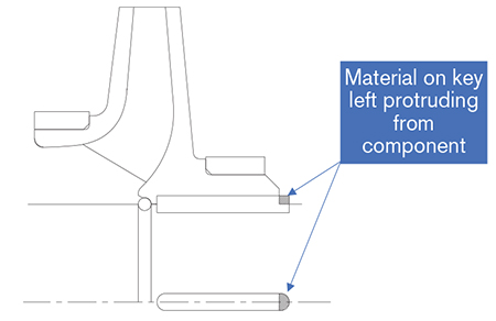
One common problem can be found in the keyway and its design. Many times, it is assumed that the keyway is filled by the key. This is rarely the case and, on occasion, the key extends out of the back of the component and may not be fitted. This can easily be corrected by using the proper fitting but is often overlooked on the coupling key.
Rotor design
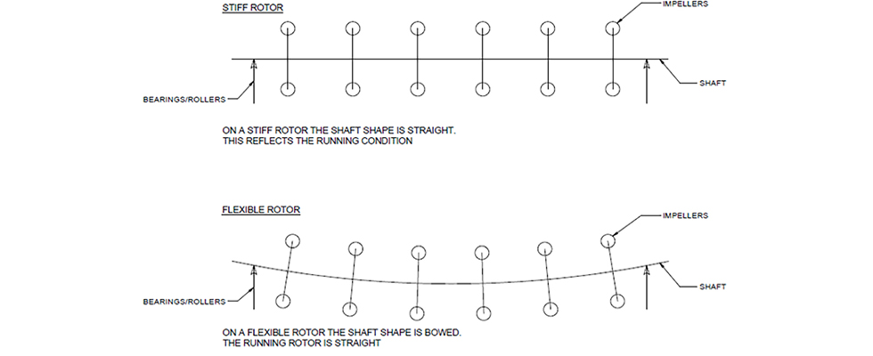
Many rotors are not classically stiff and the pump runs above the first critical speed. On a stiff rotor pump when it is placed on the hard rollers of a balance machine, there is little sag in the assemble rotating element. The running position of this rotating element when installed within the pump will correlate with the running position on the balance machine. Corrections to the balance based on the balance machine will manifest as improvements when the pump is in operation.
On a flexible rotor, the result may be very different. In operation, the force of the pressure differential across the wear rings is dominant and enough to pull the rotor straight during use. Based on this, it is important to understand the differences between the running position of a flexible rotor pump on a balance machine versus the running position of a flexible rotor pump in actual operation.
Modifications to the rotor balance based on the readings on the balance machine will not necessarily lead to an equivalent improvement in mechanical balance.
On top of this, many pump configurations require the element to be disassembled after the balance process to allow stationary wear parts and/or diffuser assemblies to be added. This disassembly destroys the balance unless it can be assured that the components can be replaced in the same position on reassembly.
Machining
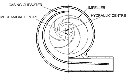
Manufacturing also has a great influence on balance. If the hydraulic center of the impeller does not exactly align with the mechanical center of the component, there will always be an out-of-balance component of vibration irrespective that the mechanical balance in air is perfect.
Attention to detail and thorough understanding are the keys to achieving a minimized out-of-balance component. Blind application without machine design consideration is rarely a successful strategy.
