

The Gulf Coast Water Authority (GCWA) provides raw water to the Texas City Industrial Complex via the Industrial Pump Station (IPS) and two transmission lines originating at the IPS. These two lines cross the industrial complex with branches supplying five major customers—Dow, BP, Valero, Marathon Petroleum Corp. and Eastman Chemical Company.
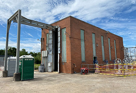
The IPS was originally constructed in 1949 with three vertical turbine pumps. Subsequent expansions in 1952, 1957 and 1965 added six more pumps for a total capacity of approximately 96 million gallons a day (mgd). Although the pumps were well maintained and functioned adequately, most of the infrastructure needed rehabilitation or replacement. The valves were in poor condition and were essentially inoperable. Visible portions of the steel discharge piping exhibited major corrosion. The integrity and reliability of the entire discharge piping and header were compromised. The pump station building’s brick wall cladding, roofing system, doors and windows also had several defects.
In 2010, the GCWA retained a national planning, engineering and program management firm to evaluate the condition of the existing pump station and develop rehabilitation alternatives. The IPS has a long history of uninterrupted service to its industrial users. Any interruption to the water supply meant these users would lose millions of dollars a day in revenue. As such, maintaining pump station operations and ensuring continuous water supply to GCWA’s industrial users during construction was of paramount importance.
While evaluating the various rehabilitation alternatives, the firm determined that the risks associated with rehabilitation far outweighed the risks associated with constructing a new pump station on the existing site. Consequently, GCWA decided to design and construct a new 96 mgd pump station on the existing site, while maintaining the existing IPS in operation throughout construction. After obtaining funding, GCWA, in February 2013, hired the firm to provide design and construction engineering services for the new pump station.
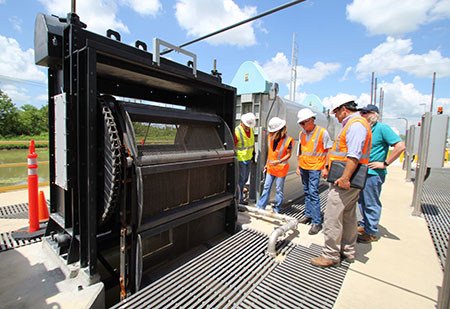
The scope of work included performing transient calculations to design surge relief facilities; site civil design of drainage and utility improvements; design of a new intake structure to accommodate three existing 5-foot-wide traveling screens and three new 8-foot-wide traveling screens; relocation of the nine existing vertical turbine pumps; new steel pump discharge and header piping, including pump control valves, isolation valves and other appurtenances; cathodic protection for buried metal piping and appurtenances; a new pump building; demolition of the existing pump building and above-grade pump discharge piping; electrical instrumentation and controls; and truck access and other miscellaneous site improvements.
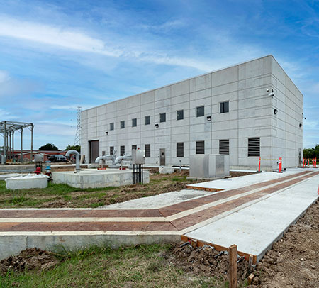
In June 2017, construction of the new pump station started. In December 2020, once substantial completion was achieved, GCWA opened the $20.04 million Joseph A. Willhelm Industrial Pump Station, named in honor of its first general manager. On July 1, 2021, the entire project was completed.
Innovative Design
Typically, when a new pump station is built, new pumps are installed. Over the decades, GCWA had maintained its existing vertical turbine pumps in almost new condition. As such, the water authority wanted to install these pumps in the new pump station. While the existing pumps have a below-slab discharge, GCWA also wanted the option to install future replacement pumps with the discharge above the pump house floor. This arrangement would facilitate removal of pumps for maintenance and eliminate the need to enter the wet well for pump removal. To accommodate this request, the discharge piping design included novel provisions for connection above or below the slab with minimal modifications.
Custom-designed type 316L stainless steel pump bases that can be easily modified without removal gave GCWA the option to install the existing below-grade discharge pumps as well as above-grade discharge pumps in the future. Two different types of pump bases were designed to accommodate both the existing variable frequency drive (VFD) and constant speed motors. Constant speed pump stainless steel bases were designed to be installed flush with the floor while the VFD bases had to be recessed approximately 10 inches below floor level. Both types of bases can be field-modified in the future for above-grade discharge pumps.
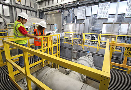
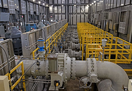
Pump discharge piping and control valves for the existing pumps were connected to the 42-inch discharge header with a straight pipe run terminating at a 24-inch by 42-inch tee. The branch of each of these nine tees was installed in a horizontal position. However, when the above-grade discharge pumps were installed, this straight piping connection would not accommodate the new above-grade discharge pipe. To address this challenge, innovative pipe connections were used to facilitate these future connections to minimize cost and installation time.
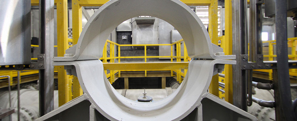
Usually, pump discharge piping is joined with bolted and gasketed flanges. However, this type of joint is not easily removed and cannot be rotated exactly 90 degrees to allow for the future vertical connection. So, instead of flanged joints, the design incorporated rigid roll-grooved joints and couplings. Sections of the 42-inch discharge header can be isolated with valves so a pump can be taken out of service and the below-grade, 24-inch pump discharge pipe and control valves can be removed as a complete assembled piece. Then, the 24-inch by 42-inch tee can be rotated to a vertical position by loosening four bolts and installing a long radius 90-degree bend, and the discharge pipe and control valve pipe section can be reinstalled.
To support this new above-grade pump discharge piping, a custom-designed carbon steel pipe support was installed with imbed bolts during the construction phase. The steel support is designed to be partially welded to the future carbon steel pipe so it will resist transients associated with pump startup and shutdown and is still removable for maintenance and repair.
Complex Challenges
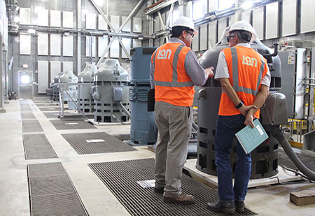
The scale and complexity of the project created numerous design and construction challenges. Chief among them was maintaining the existing pump station operations during construction of the new station to provide uninterrupted water supply to GCWA’s industrial users. Once the new intake structure, wet well, building, discharge header and yard piping at the new pump station were completed, the existing pumps were relocated one by one until operations were completely transferred to the new station.
There were periods during which both the new and the existing stations remained in operation simultaneously. In addition to reusing the pumps, three existing 5-foot-wide traveling screens that were well maintained were reused. Taking out a screen from the existing building meant that associated pumps couldn’t operate anymore. Solving this complex relocation required a specific construction sequence, detailed scheduling and extensive coordination.
Typically, when a new pump station is built, pump bases are laid out for new pumps. Since the existing pumps were being reused, the pump bases required custom drilling for the anchor bolts. During the pump relocation, GCWA and the firm worked with the millwright to install the anchor bolts in these custom-designed steel pump bases. The firm provided designs on how to transfer the pumps and fit them on the pump base, as well as the drilling location to install the anchor bolts.
Before bidding, GCWA divided the project into four phases to ensure the new pump station was up and running as quickly as possible and set project milestones for the contractor. Phase 1 involved installing underground piping for the new pump station, constructing and initial commissioning of the pump building to get the station ready to install the new pumps. Phase 2 involved relocation of the existing pumps. Phase 3 included demolishing the old pump station, backfilling a portion of the existing canal, and building the new parking lot. Phase 4 involved project closeout.
During bidding, the contractor expressed concerns over the cost/risk of relocating the existing pumps given their age. To solve this issue, GCWA assumed the responsibility of implementing Phase 2—relocating the pumps. However, the contractor got behind schedule during Phase 1 and continued working while the owner was relocating the pumps. This added another layer of complexity. Furthermore, there were also challenges when the contractor did not install some of the piping at the right location. In such instances, the firm worked with GCWA staff to make design changes on the fly to modify piping and connections.
Built for the Future
The new pump station—the single largest capital investment by the GCWA in decades—is expected to last at least 75 years, through good maintenance. Using the existing pumps has also allowed GCWA to delay some of its upfront capital costs. Over time, GCWA will gradually replace its existing pumps with new ones. Once these new pumps are installed, GCWA will be able to expand its delivery capacity by almost 25% to accommodate future industrial growth.
The new pump station is also built with sustainable materials such as stainless steel, fiberglass and concrete that provide energy efficiency, long life cycle and lower life cycle costs and do not corrode. The new pump station building was constructed with insulated structural precast concrete panels and steel framing. All below-grade structures were constructed with cast-in-place concrete for long-term durability. The building is equipped with a robust ventilation system to remove motor heat and sound attenuation panels to reduce operational noise.
Additionally, the original pump station was not hurricane-proof and was potentially susceptible to extreme weather events given its age and deteriorated condition. The new facility is designed to withstand 140-mile-per-hour hurricane winds (Category 4 wind scale)—20 miles higher than required wind load requirements. The facility’s design makes it more resilient and allows continuous operations during extreme weather events in the future.
