

There was a time when a motor operating under normal conditions, sized correctly for the application and powered by a well-balanced, clean, three-phase sine wave could last 15 to 20 years. There have even been testimonials about motors operating for three to five decades.
Since the 1980s, the industry has witnessed the rise of variable frequency drives (VFDs) with their multiple advantages, ranging from energy savings to reduced water hammer in pumps and reduced locked-rotor current. Alongside these advantages, however, came the end of well-balanced three-phase voltage signals from the grid and a reduction in motor-life expectancy. This trade-off between energy savings and clean electrical signals seems to have established itself as the new normal.
VFD Drawbacks Lead to Early Motor Failure
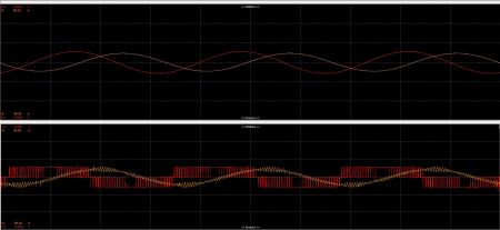
The signal VFDs feed motors with is a pulse, or square-wave, voltage and not a clean sine wave. This can lead to several drawbacks that require adding bulky filters on both the input and output side, among other compensations.
The best practices to get the full benefits from VFDs tend to be forgotten to save purchasing and installation costs. As a result, some of the disadvantages of VFDs are unfortunately becoming accepted facts. Some of these disadvantages include:
- Inherent to their square-wave output signal, VFDs are generators of high harmonics and fast rise-time voltage (dv/dt), both of which can have side effects.
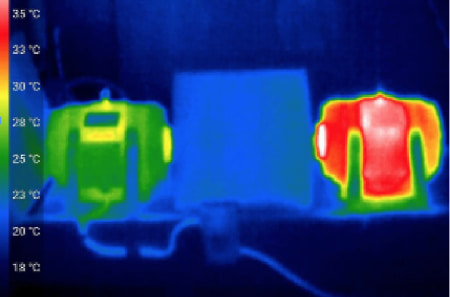
- High harmonics increase the power losses, then reduce the efficiency of the motor. Harmonics also increase the motor’s temperature, inducing degradation of the insulation material.
- Fast rise-time voltages can create spikes, also causing steady degradations of the material used in the insulation.
- Harmonics and voltage spikes can ultimately degrade motor insulation, resulting in an early motor failure.
- VFDs can induce current on the motor shaft. These bearing currents discharge through the bearings, causing pitting, fusion craters and more, eventually resulting in bearing failure and subsequent motor failure.
Mitigating Issues With VFDs
To mitigate these issues, manufacturers universally recommend some combination and/or variation of the following:
- keep the cable length between the motor and VFD shorter than 50 feet
- add a filtering device if a short cable cannot be used
- reduce the carrier frequency
- use a low-impedance ground cable from motor to VFD
- use a shaft grounding device
- add line choke/line filters on the input side and similar additions or alterations to the installation
These filtering devices, ground modifications, etc., can increase the purchasing cost of equipment, the needed volume, the wiring time and the maintenance time, and decrease installation flexibility. There is also the additional environmental and disposal impact of this added copper-intensive equipment.
But beyond the additional cost to mitigate issues with VFDs, these recommendations may not fix the underlying harmonic issues.
Addressing the Issue at its Source
The best solution to mitigate harmonics is to not generate them. Some VFDs already integrate solutions to minimize harmonic distortion but they can be expensive and bulky.
What are these solutions?
The first existing mitigation is to use a multipulse VFD. A multipulse VFD converts the three-phase input into nine or more phases (by using transformers to generate phase displacement of the three-phase input) and then creates 18 or more pulses using three or more rectifier bridges in parallel.
This solution is hindered by the volume and high weight of the transformers, cost and added losses, and the harmonics mitigation is simply theoretical. In real applications, the utility input voltages are unbalanced, and harmonic mitigation of multi-pulse drives degrades rapidly with increasing line voltage imbalance and decreasing load.1
The second existing mitigation is to use low harmonic drives. These drives embed an active front end (AFE) consisting of a three-phase insulated gate bipolar transistor (IGBT) rectifier (power electronic architecture similar to the output one). The switching method of this input allows it to achieve a total harmonic distortion (THD) below 5% as well as many other advantages such as energy regeneration and power factor correction.
Making an AFE drive as efficient as a standard drive, without generating high common-mode voltages (which are sources of bearing currents), requires a well-designed three-level architecture, an input filter and a common mode choke. When they are not integrated into the VFD, an integrator adds and commissions all of these components externally. This makes low-harmonic drives more expensive and bulkier than a common six-pulse VFD with its passive filters.
The third solution to the problem takes advantage of the latest generation of power transistors, advanced algorithms and optimized integrated filters to produce the next generation of VFDs without harmonic distortion.
Wide-Bandgap Transistors
Wide-bandgap (WBG) transistors are changing power electronics, including VFDs. WBG semiconductors offer multiple advantages, namely a more than 80% reduction in switching losses and higher operating temperatures.
These advantages can result in higher switching frequencies with lower losses, simplified cooling, operation at higher temperature and smaller passive components for filtering.
Writing specifically of WBG relevance for VFDs, the 2020 Readiness Map by 4E PECTA2 (Energy Efficient End-Use Equipment International Energy Agency’s Power Electronic Conversion Technology Annex) notes the following:
“The higher switching speed, enabled by WBG technology may […] allow for the integration of dv/dt or even sine filters with small size. By that, the use of cheaper unshielded cabling and cheaper insulation can become possible, resulting in lower cost for those components and even in a reduction of losses, otherwise caused in cables and machine windings by the harmonic content of the machine currents.”
With this solution, the industry may get an option that nips the harmonic issue in the bud while simultaneously offering a smaller footprint and permitting higher operating temperatures.
This solution may, in fact, have been around for a while: A search for articles on WBG and motor drives will turn up both trade and scientific articles spanning the past 20 years touting “higher density power modules3”, “better system efficiency4” or highlighting the challenges facing WBG designs.5
Despite their enthusiasm, even 4E PECTA does not envision products hitting the market before 2025 at the earliest.6 But this change may be closer than it seems: new WBG-based VFD architectures with integrated AFE and filters are being showcased and are delivering on the promise of a
true-sine VFD:
- reduce the THD to a level lower than required by the standard
- reduce the overall losses of the system (drive+motor)
- eliminate expensive and bulky external filters
- protect the motor lifetime expectancy
- permit the use of unshielded cabling
After more than 40 years of dominance of the six-pulse IGBT architecture, the next generation of VFDs is moving from research laboratories to design and manufacturing facilities, paving the way to offering energy savings, clean sine waves and a longer motor life span.
References
Hink, Karl M., “18-Pulse Drives and Voltage Unbalance.” MTE Corporation. mtecorp.com/pages_lang/wp-content/uploads/18pulse.pdf
Makoschitz, M. & al., “Wide Band Gap Technology: Efficiency Potential and Application Readiness Map.” 4E Power Electronic Conversion Technology Annex (PECTA), May 2020. iea-4e.org/wp-content/uploads/publications/2020/05/PECTA_Report_Total-V10final-May-2020.pdf
O’Neill, Michael, “SiC Puts New Spin on Motor Drives.” Power Electronics, Jan. 2005. powerelectronics.com/content/article/21859636/sic-puts-new-spin-on-motor-drives
Shirabe, K. & al. “Efficiency comparison between Si-IGBT-based drive and GaN-based drive.” IEEE Transactions on Industry Applications 50(1):566-572, Jan. 2014. researchgate.net/publication/260720500_Efficiency_comparison_between_Si-IGBT-based_drive_and_GaN-based_drive
Hayes, Caroline, “SiC switches in motor drive applications.” Electronic Specifier, April 2019.electronicspecifier.com/products/power/sic-switches-in-motor-drive-applications
Makoschitz, M. & al, “Energy Efficiency Policy Brief: The Energy Efficiency Potential and Application Readiness of Wide Band Gap Technology.” 4E Power Electronic Conversion Technology Annex (PECTA), December 2020. iea-4e.org/wp-content/uploads/publications/2020/12/4E-Policy-Brief-PECTA-1-271120.pdf
