
A power company in the Atlanta, Ga., area wanted to replace its older, coal-fired electric generating units with gas turbine, combined cycle technology to reduce nitrogen oxide (NOx), sulfur dioxide (SO2), carbon dioxide (CO2) and other emissions. These large turbines typically use natural gas as the primary fuel source, with fuel oil as a backup in the event of an interruption in the natural gas supply.
The manufacturer selected to supply the turbines on this upgrade project previously had to manage installation of the secondary fuel oil system as an onsite construction project that proceeded in numerous stages. That approach required considerable time and associated expenses to specify, order, ship and install equipment, including pumps, motors, filters, bypass valves and piping, monitoring panels and other crucial components.
A better solution was needed, and a fluid-handling company with experience in the power generation industry manufactured a preassembled packaged module, designed as a single, integrated fuel oil system that could be shipped to the utility on a frame, ready for quick installation.
Secondary Fuel Source Considerations
The choice of secondary fuel used at power plants varies worldwide, based on availability and cost, but the most common options are naphtha, natural gas liquids, crude oil, bunker fuel oil and distillate (No. 2 fuel oil).
Each fuel has its own unique requirements-including treatment or cleaning/filtration-to minimize excessive erosion or corrosion to the hot gas parts of the turbine. If initial viscosity is high, fuel heating might be necessary to reduce viscosity to a manageable level.
For this project, Grade 2 distillate fuel oil (American Society for Testing and Materials [ASTM] standard) with a typical low viscosity range of 33 to 48 Saybolt Universal Seconds (SSUs) was chosen.
Regardless of fuel used, reliability is a key element in the selection of components for handling it, particularly in an application as vital as electric power supply.
Designing a Fuel Oil Pumping Solution
Many firms use advanced 3-D computer aided design (CAD) product engineering modeling software programs to draft systems and modules. The images provide a visual scope of supply, component verification and general arrangement layouts.
A fluid handling system manufacturer used such a program to demonstrate how an integrated system with fuel filtration, main fuel oil injection pump, preferred electric motor, instrumentation, piping and components would streamline secondary fuel delivery. The 3-D CAD renderings significantly enhanced communications with the turbine manufacturer throughout the project.
This approach also had the benefit of reducing the number of shop engineering change notices, which in turn reduced the total manufacturing cost. Another advantage was that modules could be designed to fit standard size intermodal freight shipping containers, which lowered logistics costs. (See Figures 1 and 2.)
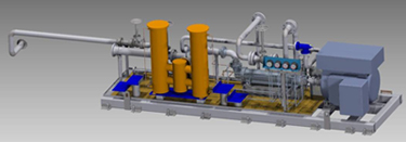
Figure 1. 3-D modeling
.jpg)
Figure 2. Intermodal baseplate. The fuel oil system developed for the gas turbine manufacturer was installed on this 20 ft. base , which occupies less space than the equipment typically used by power generation plants and fits into a standard intermodal container for shipment.
Through empirical testing and analysis, three-screw pump scientists developed flow charts depicting pressures, flows and horsepower based on viscosity range, then selected the correct pump model to lower risk and provide maximum flow assurance. The filtration unit and pump were specified and sized accordingly to meet the turbine's fuel pressure/flow requirements for this low viscosity fuel, which is intended to be used with a high discharge pressure fuel injector.
Manufacturing and Assembly
A rotary, positive displacement, three-screw pump technology was chosen for the main fuel oil injection pump, based on years of proven success in distillate fuel oil applications worldwide. This technology works well in low viscosity applications, as well as at higher viscosities, such as some crude oils and all residual fuels. The application has a normal discharge of 100 bar (1,450 psig), with relief-valve setting at 120 bar (1,740 psig). Delivered flow of a simplex pump per turbine is approximately 360 gpm. (See Figure 3.)
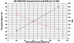
Figure 3. Typical performance curve
Having a positive pressure system parameter of three to 10 bar (29 to 145 psig) at the inlet point into the fuel oil injection system from the low pressure fuel oil supply forwarding pump allowed for correct sizing of the filtration unit, based on maximum 25 psig allowable pressure drop across the filter, combined with the NPSH required for the pump. Based on the fuel characteristics, a 316 stainless steel duplex-cartridge filter assembly (beta 15, 330 International Organization for Standardization [ISO] grams dirt-holding capacity) was engineered and constructed to meet ASME Code Section VIII, Division 1, which governs pressure vessels.
With the filter, pump, 500 hp electric motor and other key elements selected, construction began. Welding, pipe-fitting, valve installation, inspections and performance testing were completed to exacting industry standards by trained employees working in a climate-controlled shop, which eliminated the effect of weather on production that could occur in a more exposed environment, such as during onsite construction.
.jpg)
Figure 4. Rotary positive displacement pump. An advanced technology, high pressure, rotary three-screw pump is on the right.
Engineers and project managers regularly consulted with workers on the shop floor. Additionally, careful attention was given to lighting, tooling placement, quality control and other manufacturing condition and process elements to ensure fast production and adherence to product specifications. The finished module equipment was delivered preassembled and ready for installation, with minimal onsite work.
.jpg)
Figure 5. Reduced footprint. The fuel oil system used less than 15 ft. of stainless steel piping--a significant acheivement providing reduced footpring at the utility and lower material cost.
.jpg)
Figure 6. A single package. The fuel oil injection module was an integrated unit containing filtration, fuel injection pump and motor, valves and piping.
Project Manager: Coordinating the Entire Process
Timely response is a frequent "pain point" cited by manufacturers, engineering, procurement and construction firms, and end users. Eliminating the number of component vendors and their multiple contacts enables faster response and higher productivity. Realizing this, the fluid-handling company establishes a project manager to coordinate the entire process for each order and serve as a single point of contact for the customer. In this application, the project manager oversaw activities including initial design, drawing transmittal, revisions and the ISO 9001 quality manual audit, all of which facilitated communications and ensured schedule adherence.
Savings for This Project and Other Industries
The fuel oil injection pump system supplier team significantly reduced costs associated with multiple component designs, arrangement and installation. Additionally it cut the product footprint by approximately 30 percent. Cost savings extended beyond the system for procurement, engineering, testing and validation, and energy consumption. Single source supply also cut the customer's travel costs for inspections, which further reduced overall procurement expenses.
A packaged system worked well for this utility application, but it is also appropriate for other major industrial markets, such as petroleum offshore production and remote processing facilities, to save on purchase, shipping and logistics, and onsite construction.
Pumps and Systems, July 2010
