

In my previous article (Part 1, Part 2), I wrote about the criteria needed to make proper selections for residential and light commercial packaged pump stations. In a continuation of that theme, we will speak on a more advanced level with a focus on prepackaged, submersible pump stations for commercial and municipal sewage applications. Following the steps detailed in this article will continue to leave each flush a mystery.
The same data needs to be gathered for larger applications as is needed for residential applications. I have added the same questions to this article with a few added notes that pertain to larger applications. However, municipal regulations vary from state to state and city to city. This article is to serve as a guide to get you in the right line of thinking. Be sure to familiarize yourself with your local regulations to ensure your design is compliant and smooth over the course of the submittal process.
Pump
Similar to residential, there are two primary types of submersible sewage pumps: solids handling and grinder pumps. Grinder pumps offer more robustness to varying pressures and water quality, and solids-handling pumps produce more flow at greater efficiencies. Given the wider range and generally more abusive applications for municipal use, pump selection should be specific to each application. Generally, these pumps are built to order, allowing the municipality or specifying engineer to select features such as materials of construction, cooling features, bi-directional operation, inverter duty, explosion proof, high temperature, coatings, etc. Manufacturers can assist in selecting which pump type and upgrades to employ. The important aspect in sizing municipal stations is determining an appropriate flow rate and an accurate system head curve to aid in the selection process.
Flow rate calculations for municipal applications differ from residential. Residential applications are typically sized using the fixture unit method, where each water producing fixture impacts the size of the sewage system. However, on a larger scale application, such as an entire neighborhood or commercial office building, the fixture unit method would be overly conservative. Alternatively, the population method is typically used. The population method applies an estimated daily design flow (DDF) to each unit of population. This may be 100 gallons/capita/day for a residential development, or it could be 15 gallons/employee/day for a commercial facility. Dividing the total DDF by 1,440 gives the average gallons per minute (gpm) flow rate. To ensure the pump and basin can handle the variations in waste flow throughout the day, a peaking factor is multiplied to the DDF. The peak factor typically ranges from two to four and is dependent on the population size. Waste flow from a large population is less variable, allowing for a smaller peaking factor nearing two. Small populations have greater variability and require higher peaking factors near four. The peak DDF can then be derived to a gpm value to size pumps and basins. Be sure to check local regulations for added requirements such as allowance for inflow and infiltration (I&I) and other parameters.
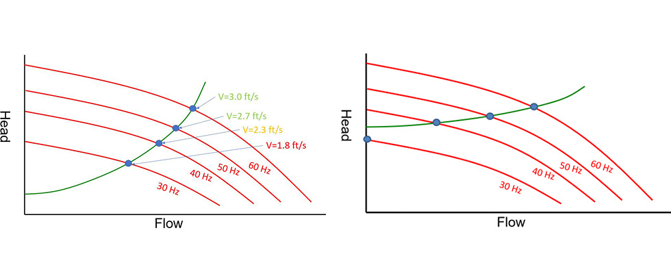
System head curves are critical in municipal pump station designs. System head curves are a graphical representation of the total dynamic head (TDH) in a system at varying flow rates, essentially a performance curve of the piping network. System head curves provide additional insight as to how a pump will operate within a system, providing valuable data such as the operating point. Systems with varying operating points such as pumping over high points, large drawdowns leading to a change in static head or force mains with pressure fluctuations will have multiple operating conditions and require multiple system head curves. Identifying all critical operating conditions will allow the designer to select a pump that can safely operate under all conditions. System head curves are also critical anytime a variable frequency drive (VFD) is used. As the frequency lowers and the speed of the pump changes, the head and flow produced by that pump are also reduced. The benefit is the pump can meet varying operating conditions at a fraction of the power input, boosting overall efficiency and extending the pump’s life. The possible catch is a pump may operate at a flow rate less than 2 feet per second (ft/s) or even dead head in systems where the majority of the TDH is due to high static head. See Images 1 and 2 for examples of each. If this is the case, does that mean a VFD cannot be used? No, a VFD could still be used, but the programmer needs to set the minimum operating frequency where the pump does not dead head or produce low velocities, which requires a system head curve to ensure the added investment is cost effective and applicable.
Basin
The basin is sized after the pump, as the basin’s size is driven by the pump’s physical size and the flow rate produced by that pump. With municipal and commercial applications, the one-size-fits-all approach no longer applies. To simplify basin sizing, it is best to break the basin down into four different zones:
Minimum area (diameter or length x width [LxW])
Inlet depth (I)
Working volume (WV)
Minimum liquid level (MLL)
Reference Image 3 for a representation of each.
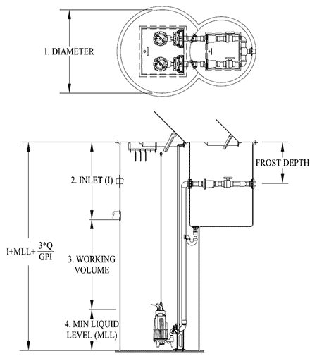
IMAGE 3: Basin details
The minimum area is mostly a factor of the physical size of the pumps, their separation from other pumps and walls to prevent vortices as well as the plumbing inside the basin. Manufacturers should be consulted to identify the minimum area needed to house the pumps, rails, plumbing and valves to ensure proper spacing and fitment. In some cases, flow rates, inlet depths and other factors may dictate using a larger area to provide additional volume per unit of depth.
The inlet is the drainpipe that brings waste into the basin. If multiple inlets are feeding the basin, the lowest inlet’s depth or elevation is needed to properly size the basin. Under normal circumstances, the water level in the basin should not exceed the level of the inlet to prevent water backing up in the drainpipe and potentially in the building. Therefore, the inlet establishes the maximum water level and, as such, is the primary driver of basin depth. In some instances, the incoming sewer pipe can provide additional storage for abnormal conditions; however, be cautious of the lowest sewer tap or overflow upstream of the basin. The minimum liquid level is dependent on the pump used. Submerged pumps will dissipate heat better than a pump running in air. As a result, it is best to size a basin that keeps the pump fully submerged. This is easily done by setting the off point at or above the top of the pumps. Therefore, the minimum liquid level is typically the height of the pumps. If applicable, the net positive suction head required (NPSHr) may require a higher off point to prevent cavitation. The manufacturer shall be able to provide both the NPSHr and height of the pump to ensure you are covered for both.
Lastly is the working volume. The working volume is the total usable volume between the minimum liquid level and the lowest inlet. This includes the off, on, lag and high water set points. It is critical to ensure that there is enough volume to prevent short cycling—the rapid succession of turning a pump on and off, leading to premature failure. The industry standard is to design a basin for a maximum of 10 cycles per hour, though manufacturers should be consulted for the exact number of cycles a pump is rated for. A cycle includes both the fill and draw down time between the off and on point in the basin. Assuming a constant inflow, the worst-case scenario occurs when the incoming flow is half of the pump’s flow. Under this assumption, the minimum drawdown volume to prevent short cycling is given by Equation 1:
Vmin = (Tmin*QP)/4
Where:
Vmin = Minimum Volume (gallons)
QP = Pump Flow Rate (gpm)
Tmin = Minimum Cycle Time (minutes)
For a system designed for 10 cycles per hour (6-minute cycle time), the minimum volume between the off and on point would be one and a half times the pump’s flow rate. Also, some additional volume is needed for the lag and alarm set point as well as any storage requirements. For the alarm and storage requirements, it is best to check with local regulators. A good starting point is to provide a total working volume that is double the minimum volume. Therefore, as a general rule of thumb, where 10 cycles per hour is acceptable, the working volume is equal to three times the pump’s flow rate. To convert the working volume to a depth, simply divide by the volume per unit of depth. The minimum working height should be 24 inches or greater to provide adequate spacing between off, on, lag and high water set points or floats. Assuming 10 cycles per hour, Equation 2 below gives a simple way of determining the basin depth. Be sure all measurements are in the same unit (inches, feet, meters, etc.).
Basin Depth = Inlet Depthin
+MLLin+(3*Q)/GPI
Where:
Q = Pump Flow Rate (gpm)
GPI = gallons per inch
