
Pump System Improvement
Engineered Software Inc
02/10/2017
Engineers involved with any project that includes more than a cursory amount of digging must consider how to manage groundwater. Whether construction-site preparation, pipe trenching going down tens of feet or mining operations going down hundreds of feet, water from runoff or seepage must be removed from the work area and, in many cases, must be treated in some way before being discharged back to the surrounding environment. This column explores some of the challenges associated with water removal from work sites. While dewatering systems typically are relatively simple in structure, they highlight some of the less obvious complexities associated with piping systems. Consider a site with two drainage sumps (see Figure 1).
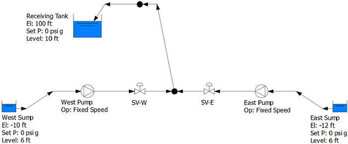 Figure 1. System diagram of a site with two drainage sumps (Graphics courtesy of the author)
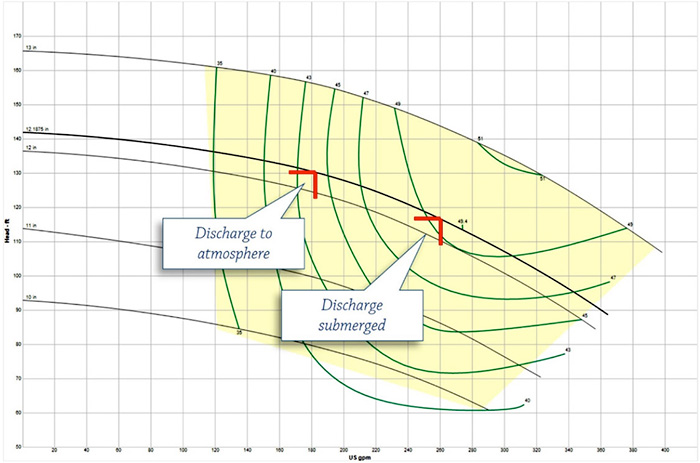 Figure 2. Comparing pump operation when discharging to atmosphere and discharge submerged
Control Methods
Depending on the seepage rate, the dewatering pump may operate continually or may be turned off and on based on the water level in the sump. This represents another control in the system and highlights a key point: Control methods range from quite sophisticated to very simple depending on the application. In this case, it may be a simple on-off float switch, or a manual switch that is driven by the operator following a procedure to visually check and flip the switch when the sump gets to a specified level.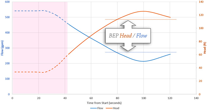 Figure 3. Pump performance during fill time without a control element
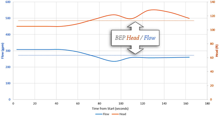 Figure 4. Pump performance with manual valve adjustment
Valve Positioning
Using our system model, we can determine the best valve position and fill time by evaluating the static head on the pump over time. In this example, setting the valve at 50 percent open at startup, then opening the valve to 90 percent after 90 seconds was determined to be an optimum process involving only one adjustment and minimal operator attention. Regardless of the control method, we can see that the pump, process and control elements all work interdependently to determine the total system behavior. Instrumentation and controls such as level indicators, float switches, regulators and manual valves are an integral part of the system, ensuring it operates within the range of acceptable conditions, preventing overflow, spillage or equipment damage.Multiple Pumps
Lastly, it is common in dewatering situations to have multiple sumps feed into a common header, so the interaction of multiple pumps is something that must be considered. In our simple model, the addition of the East Pump has only a small negative effect on the performance of the West Pump, pushing the operating point away from the BEP. In systems with multiple sumps, wellpoints or deep wells, multiple-source elevations and pumping into common headers can have significant effects, including reversing flows and causing pump damage as various pumps are brought on- and offline. A full system analysis looking at different scenarios will lead the engineer to a greater understanding of the interactions between the pump elements, determine the most critical areas within the process elements, and find the most efficient locations and controls to operate the system in all situations. As discussed, even a simple dewatering system has all the elements of more complex piping systems—pump elements, process elements and control elements—as well as all the same problems large systems experience. Taking steps to mitigate these problems, even simple steps such as extending discharge piping or adding a well-placed manual valve, can have a positive effect on uptime and operating costs.
To read more Pump System Improvement columns, click here.
