

Motors and generators are often critical components of electrical systems. Additionally, they are used to automate many industrial processes, transport and/or circulate liquids for cooling and lubrication purposes, and generate electricity, to name a few applications. If there is an unplanned interruption of these processes due to the failure of one of these rotating machines, the resulting damage, downtime and inability to perform crucial work can have costly repercussions. For this reason, a great deal of emphasis has been placed on how to ensure the health of electrical systems and processes.
The failure of rotating machinery can often be attributed to the degradation and/or contamination of the insulation that separates electrically energized components from one another and the ground. The insulation is the most sensitive part of rotating machines and is, therefore, important to the continued health and operation of rotating machinery.
Power Factor (Dissipation Factor) Testing
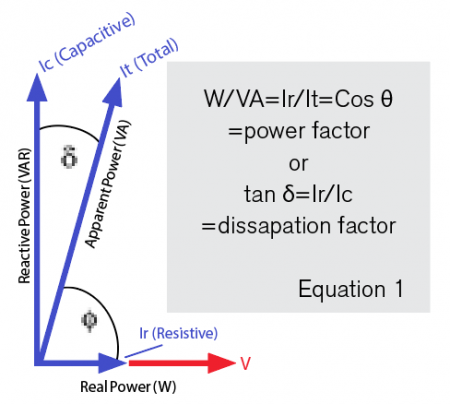
Although not always required, one of the tests often performed on rotating machinery is an AC insulation test, commonly referred to as either a power factor test or a dissipation factor (tan ẟ) test. Although, these two measurements are calculated differently (Image 1), for modern stator winding insulation systems, the power factor and the dissipation factor are often used interchangeably. Power factor and dissipation factor are unitless measurements of the losses that occur in insulating materials and are reported in terms of percent. They are considered diagnostic tests due to their ability to be trended over time and to give insight regarding changes that are occurring in the insulation of electrical apparatus such as motors and generators.
An ideal insulator is a perfect capacitor that has no losses and where current leads voltage by 90 degrees. In this case, the power factor, or cosine of the angle between voltage and current, would be zero. However, in reality, there is no such thing as a perfect capacitor (insulator). There will always be some small amount of leakage current. Coil systems like those found in electric motors have inherent losses causing both capacitive and resistive current flow. So, a realistic and desirable value of power factor or dissipation factor can be small in a good insulating system, but it can never equal zero.
The primary reason for power factor or dissipation factor tests on rotating machines is to assess the extent of void formation associated with dry-type insulation. Ionization of these voids equates to increased dielectric losses and the deterioration of the insulation over time. Additionally, an overall power factor measurement on winding insulation will reveal when there is abnormal deterioration, potentially due to phenomena such as partial discharge and/or ingress of moisture and other contaminants.
These tests are typically performed at a single voltage that does not exceed the line-to-neutral rating of the apparatus. Performing the tests at the same voltage every time over the life of the apparatus allows results to be trended and compared to differentiate between gradual changes that would relate to a normal aging process as opposed to more significant changes that give predictive insight into when mitigating actions need to happen to prevent unplanned failure. Perhaps a good analogy would be that of a person who grows old gracefully as opposed to one who falls and injures themselves.
Power Factor Tip-Up Tests
While power factor testing applies to most types of insulation, power factor tip-up tests are primarily applicable to dry-type insulation such as is found in dry-type transformers and rotating machinery. Performing power factor testing of motor windings can serve as a baseline measurement for trending purposes over time. A power factor (dissipation factor) tip-up test is a variation of power factor testing that is widely used to identify voltage dependencies in winding insulation. Information regarding this topic is available in the Institute of Electrical and Electronics Engineers (IEEE) 286-2000, “IEEE Recommended Practice for Measurement of Power Factor Tip-Up of Electric Machinery Stator Coil Insulation.”
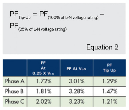
To better understand the value of power factor tip-up, first define what it is and how it differs from a standard power factor test. The power factor tip-up is defined as the difference between the power factors measured at two designated voltages applied to an insulation system, other conditions being constant (see IEEE 100 “Authoritative Dictionary of IEEE Standards Terms”).
In this test, the power factor is measured at two different voltages. The first test voltage is often conducted at 25% of the rated line-to-neutral voltage. This should be a low enough voltage that ionization of voids (partial discharge) within the insulation has not yet begun to occur. A second power factor test is performed at 100% of the rated line-to-neutral voltage. The tip-up value is derived by subtracting the value of power factor at the lower test voltage from that of the value of power factor at the higher test voltage.
Greater resolution to the characteristic of power factor tip-up will sometimes be attained by testing at additional voltages between 25% and 100%. For example, power factor tests may be performed at 25%, 50%, 75% and 100% of rated line to neutral voltage and then plotted to give a visual indication of an insulation’s voltage dependency (Image 2).
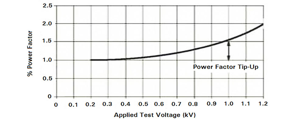
The amount of increase in power factor value as a function of voltage corresponds to the degree of ionization taking place in voids. It serves as another means by which dry-type/solid electrical insulation can be evaluated to determine the extent of insulation deterioration because of its voltage dependency.
There is more to know and understand about the electrical tests that can be, and often are, applied to different types of electrical insulation. However, the goal of this article is to specifically show how power factor tip-up tests can be a valuable tool in identifying when voltage dependencies of dry-type electrical insulation are changing. In addition, the intent has been to point out how these changes are another tool in characterizing the deterioration and/or contamination of insulation found in rotating machinery.
It is important to recognize the diagnostic capability of these tests. Trending test results provides insight into the condition of the insulation as well as scheduling of maintenance and repair. It will also aid in understanding the life expectancy of rotating machinery and, thereby, guide decisions related to the timing of motor replacement to avoid costly and unexpected failures of motors and the processes of which they are an integral part.
References
“IEEE Recommended Practice for Measurement of Power Factor Tip-Up of Electric Machinery Stator Coil Insulation,” in IEEE Std 286-2000, vol., no., pp. i-29, 2001, doi: 10.1109/IEEESTD.2001.92415
“The Authoritative Dictionary of IEEE Standards Terms, Seventh Edition,” in IEEE Std 100-2000, vol., no., pp.1-1362, 11 Dec. 2000, doi: 10.1109/IEEESTD.2000.322230
