

The accuracy of pump hydraulics is often a matter of practicality versus theory. Experienced engineers working with pumps are rarely bothered with exact details of the application when they are “ballparking” a pump need. From years of experience, they know that neglecting velocity head correction, gages elevation adjustment, the “Reynolds number” on the friction losses estimate are negligible. While they occasionally run into trouble by using such shortcuts, they remain reasonably safe and accurate enough in getting to their ultimate objective: getting (roughly) a good pump for the pumping they need done.
It is not that experienced practicing engineers are unaware of the pitfall of cutting corners or avoiding basics, but that they know their “way out” in case they make a mistake, and they (usually) also know when to do a quick, rough estimate, and when a detailed, painstaking analysis of hydraulics is required.
For a young student in college, lacking such experience in the field and not yet having learned how to wheel out of major pitfalls in the real world should he or she get there, such simplified life practices are not a good option. Besides, they need to get a good grade on their project and learn the fundamentals so they eventually can enter the practical world and only then move on to taking chances.
I recently was involved in helping a young engineer to better understand the pump hydraulics basics. Interestingly for me, the questions my apprentice asked were refreshingly pointed. I found myself having to think about how to answer properly so that my answer would be clear, simple, and yet with enough details for him to understand how pump hydraulics really work.
I hope the reader will also enjoy the logic of the problem flow, as well as get some additional practical opportunity to work with the metric system, since the project was in the Middle East. Therefore, flow would be in cubic meters (m3) per hour or second and head in meters.
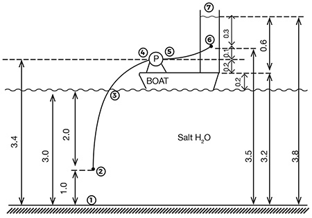
Image 1 describes the application. A group was assigned a project of designing a small, remote-operated boat, with a small pump and collection tank, to take a sample of water from the Dead Sea. The water has a very high salt content, and samples would need to be done at various depths at various times.
The average depth from the water level to the sea floor is 3 meters, and an example shows a suction pipe (or tubing) dropped to the 2-meters depth sampling case. The pump needs to “lift” water to its entrance, and then pump to a sampling tank, which is 0.6 meters tall, but the discharge tube is inserted into it at some intermediate level (about 0.3 meters from the surface of the tank). The significance of our notations in Image 1 will become clear later.
Operating parameters were to obtain about 4 liters of water quickly (about half a minute), and so the flow rate was established as 8 liters/sec = 1.3 x 10⁻⁴ m3/sec = 0.48 m3/hr (about 2 gallons per minute [gpm]).
and d = sqrt (A x 4/pi) = 0.0075 m = 7.5 mm
(A = tubing open area, d = diameter)
Equation 1
The group also felt the tubing size should be small enough to be easily rolled, but not too small that the salt deposits would plug it up and settle between the samplings. Five to 15 millimeters (mm) size was deemed proper, and when they asked me for an advice, I suggested to use roughly 3 m/sec velocity in the pipe as the starting criteria.
This satisfied the selection criteria.
Once the tubing size was known, the next step was to calculate the losses (friction plus static) for the flow, and from these, the pump match could be selected.
Understanding the concept of pump head was the biggest challenge for the students of the project group, and this is the reason Image 1 shows the details of the flow path. The students initially had a hard time understanding from which point does the pump actually begin to pump—from the entrance to the tube (2), from the surface of the water (1), from the entrance to the pump (4)? And up to which point does the pump work to move the water—point 5? Or 6, where the tubing ends? Or 7, the surface of the sampling tank?
Over the years of working with pumps and pumping systems, I learned to take for granted that the pump head is equal to static head (the difference between the water levels at the tanks), plus friction losses in the discharge piping, and so I had to go back to the fundamentals to explain to the students the idea.
A pump does nothing at the suction side. The atmospheric pressure does. It has to move the water from point 2 to 4, and only then the pump will take over. Initially, the suction pipe needs to be primed (how is another question, of which we are not dealing here), and so when the pumping starts, the motion of fluid will cause hydraulic friction, reducing pressure from the inlet to the tube (point 2) all the way to the pump inlet (4), where in fact the pressure would be below atmosphere, i.e., partial vacuum.
The pump will add energy to the water, increasing its pressure between its inlet—4 to 5. From there, pressure at 5 would have to overcome friction in the discharge tubing length (5 to 6), plus static head between 5 and 7. Positioning of point 6 is irrelevant. Both concepts took time to understand, but eventually the group got it, and I believe they will remember it for good.
To illustrate, let’s tabulate what the static pressures are along the flow path:
- bottom of the sea = +3 meters
- tube entrance = +2 meters
- inside the tube at the level of water = 0 meters (i.e., equal to atmospheric pressure)
- pump entrance = -0.4 meters (slight vacuum—and will be even lower once the fluid moves and friction losses would drop the pressure further)
- pump discharge = to be determined
- end of the tubing = +0.3 meters (determined by the open surface pressure—atmosphere—plus water depth above the tubing in the tank)
- tank surface = same as 3, i.e., 0 meters (atmospheric)
It shows that, whatever extra pressure the “submergence” is adding at the suction side moves the water to the pump inlet and any extra submergence (elevation) on the discharge side is up to the pump to overcome. The pump head is simply the difference between pressures at 5 and 4. And thus, these are the pressures we would need to know.
What about the friction losses, to help adjust the static pressures?
Where:
f = friction coefficient
L = pipe length
d = pipe diameter
V = velocity
g = gravitational constant (9.8 m/s2, in metric units)
Equation 2
A practicing engineer would probably pick friction a f=0.03, as it is most common value. But a student wants to know why, and so, per the Moody diagram, it is a function of the Reynolds number:
Re = V x d / visc
That also caused our group a pause—what is the viscosity of the Dead Sea’s water? To answer this, I called an engineering manager at Dead Sea Works and got a “roughly 1.03 centistokes (cSt)” number. In the meantime, our group looked up other sources, and found tabulations showing that “saltwater viscosity ranges averaging about 1.15 cSt, and specific gravity about 1.03 inches.
With that information, the Reynolds number would be:
Re = 3 m/sec x (7.5/1000) m / 1.03 (or 1.15) x 10-5 m2/sec = between 2250 and 2520
Depending who you trust, and from the Moody Diagram, the friction coefficient comes out to be near 0.03.
Friction loss on the suction side
(2 meters of length, 7.5 mm tube) = 0.03 x 2 m (1000 mm/m) / 7.5 mm x 32/2g = 3.8 meters
And at the discharge side it would be:
= 0.03 x 3 m (1000 mm/m) / 7.5 mm x 32/2g = 5.7 meters
Thus, the adjusted static pressures at 4 and 5 would be:
Hs = -0.4 – 3.8 = - 4.2 meters
Hd = (+0.3 + 0.1) + 5.7 = + 6.1 meters
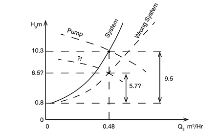
And the pump head, H = Hd - Hs = +6.1 – (-4.2) = 10.3 meters, of which 0.8 m is to overcome static head difference between water levels, and the remainder 9.5 meters is the combined friction of the discharge and suction sides.
And so, had we neglected friction losses at the suction side and simply added discharge friction (5.7 m) to the static head difference between the tanks—3.8 – 3 = 0.8 m—we would have H = 5.7 + 0.8 = 6.5 meters, a rather significant difference.
Our pump selection now should be for Q = 0.48 m3/hr, H = 10.3 meters (and not 6.5 meters). The power required to drive such a pump would be small, probably a 12-volt direct current (DC) supply, and if it is a centrifugal, the pump curve would intersect the system curve as shown on Image 2.
Image 2 shows a centrifugal pump properly selected based on the correct system calculations. It also shows a case that if suction losses, as illustrated in this example, were not accounted for, the wrong pump would have been selected based on the wrong system.
I hope readers enjoyed digging into the guts of pump hydraulics basics and the error of brushing off the suction side considerations. As parting questions to our readers: How bad would this mistake be? In other words, a pump selected incorrectly, as illustrated—will it not work at all? Or, will it still do something useful? Let us know—the best answers will receive free admission to our next Pump School session.
