

In the September 2020 issue of Pumps & Systems, we discussed the proper selection of a pump for a given system. A discussion of the system’s hydraulics details included a case where suction piping losses were disregarded, resulting in a wrong selection of the pump. Images 1 and 2 from the September issue (Part 1) are reproduced here as a reminder for our readers.
At the end of the column, we included a parting quiz: What would actually happen if the pump was selected not based on the correct system (including the suction losses component), but on an incorrect system where these components were not accounted for? Point A was selected to move 0.48 cubic meters per hour (m3/hr) at 10.3 meters of head—instead of Point B, which would have selected a pump for the same flow but lower (suction losses not accounted for) head of only 6.5 meters.
Yet, if the pump was selected based on Point B, installed, and pumping against the correct/real system, the pump would simply slide along the curve toward lower flow (Point C), and pumping—judging from the rough scale about 0.35 m3/hr and about 7 meters head. The power curve is not shown, but generally the power is lower at a lower flow. So, the pump would consume less power (i.e., no danger of motor overload).
In many cases, generally speaking, a flow reduction from 0.48 to 0.35 (about 30 percent flow loss) would be considered problematic. Going back to the case outlined in Part 1, this small pump is used strictly to periodically sample water at the Dead Sea and a difference in sampling time between just half a minute or 1 minute is essentially insignificant for the sampling crew, and thus, not a practical issue.
A reader, Mark Trumble (Response 1), answered our quiz question in general terms, pointing out that the pump would not be operating at the desired flow. Another reader, Lee Ruiz (see Response 2), offered additional feedback to the posed question. Ruiz touches not only on what effect a neglect of suction losses would have on flow, but also on ways to fix the problem should the flow need to be maintained and to reduce the losses via resizing the discharge/suction tubing, which is an easy thing to do for such a small (sampling) pump size. I wish to thank Ruiz for his usual insight and good comments. As far as his notes on actual viscosity and specific gravity of the Dead Sea water, I would tend to go with the numbers provided to me by the engineering manager at the actual Dead Sea Works, and not trust the internet values in this case. However, I will pass along Ruiz’s quoted values to see if we get any additional comments from the Dead Sea Works engineers.
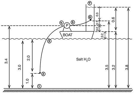
IMAGE 1: System arrangement, dimensions are in meters—tube length between 5 and 6 meters (Images courtesy of the author)
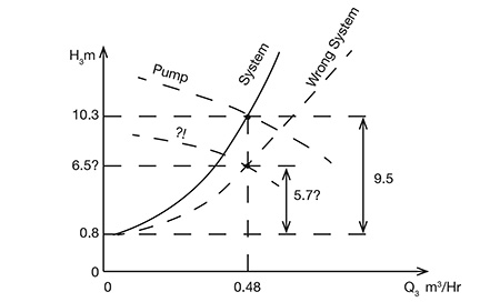
IMAGE 2: The system must account for the suction side losses
Response 1:
I very much enjoyed your review and approach to hydraulic fundamentals. My reply to your question about pump selection may be: within a “ballpark range,” the pump would likely move the fluid but not at the desired flow rate. Issues [would be expected] with the life of the pump (wear, cavitation).
Mark Trumble
Director, Cross Country Infrastructure
Houston, Texas
Response 2:
In your latest P&S article, “Pump Hydraulics Fundamentals: A Student’s View,” you described an application for sampling saltwater from the Dead Sea. A parting question was raised about how bad it would be to select a pump based on omitting suction-side friction losses.
Well, per the rough pump curve in Image 2 that passes through 0.48 m3/hr and 6.5 meters (m), it appears that an incorrectly selected pump with the selected tubing might not meet the head requirements even with excessive throttling. However, using the given input data and calculations for a proper pump selection, the incorrectly selected pump should be adequate for this application if the required head at 0.48 m3/hr could be reduced by about 3.8 m (10.3 m - 6.5 m).
It turns out that a 9 percent to 10 percent increase in tube I.D. should reduce the velocity and friction losses enough to meet the revised 6.5 m head requirement at the required 8 liters per minute (L/min), or 0.48 m3/hr flow rate. Then, the incorrectly selected pump can still be used (flow velocity would drop from about 3 meters per second [m/s] to 2.5 m/s).
Per Image 1, it appears that the selected 2 m of suction-side tube length may not be adequate; a 2.5 m to 3 m tube length might be better. If the suction tube is lengthened, a reevaluation of tube I.D. sizing versus the new friction losses might be considered.
It may not make a significant difference with required head and power in this application; however, online values for specific gravity and viscosity of Dead Sea water were found to be a bit larger than the article values. Specific gravity was shown at 1.24 and a dynamic viscosity of 3.6 centipoise (cP) was found.
Lee Ruiz
Oceanside, California
Response 3:
In your article, you state “positioning of Point 6 is irrelevant.” This neglects the fact that when the pump is first started and the water level is below Point 6, then Point 6 is the discharge elevation. I realize you were trying to cover the basics in this article, but I’ve seen young engineers get into trouble not considering all the possible conditions a system needs to operate under. I, myself, have designed a number of systems pumping to tanks in which I ran the inlet pipe up high either through the tank wall or an internal standpipe because the pump head variation due to a low entry point in a tall tank made pump selection unfeasible.
I enjoy your and Jim Elsey’s articles a great deal.
Larry Fettkether, PE
Jacobs Engineering
Response 4:
I just read the above referenced article and noticed a small error. Just before Equation 1, you established the flow rate as 8 liters/sec. It should be 8 liters/min.
Mark Gilbert
Project Manager-Water & Wastewater, KSB, Inc.
Henrico, Virginia
(3.6 cg/cm-s) / (1.24gr/cm3) ≈ 2.90 x (0.01 cm2/s) ≈ 2.90 centistokes (cSt)
Equation 1
To read more Pumping Prescriptions columns, click here.
