These devices can detect problems and provide information needed to improve efficiency and save money.
Endress+Hauser

Companies incur thousands, if not millions, of dollars in maintenance costs to keep their pumping systems in good health. Predictive maintenance is one of the best ways to cut pump operating costs. One effective predictive maintenance technique uses an electronic differential pressure transmitter to not only monitor instantaneous pump performance, but also to identify issues related to pump health and efficiency.

Optimal pump operation zone
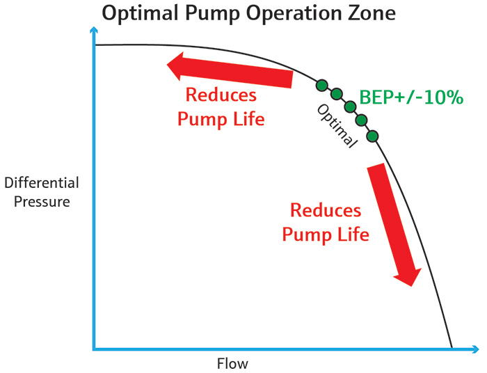
Figure 1. The BEP is 70 to 85 percent of the maximum differential pressure between the suction and discharge pressure. (Images and graphics courtesy of Endress+Hauser)

Monitoring Differential Pressure

All pumps perform best when they are at, or very close to, their best efficiency point (BEP) (see Figure 1). The BEP is defined by the manufacturer on its pump curve and is typically 70 to 85 percent of the shut-off head or maximum differential pressure between the suction and discharge.

Operating at the BEP is the single most important aspect for prolonging pump life and cutting maintenance time and costs. An electronic differential pressure (EdP) transmitter is well suited for monitoring the performance of a pump in applications where continuous operation is critical, such as cooling tower systems or aeration pumps in wastewater treatment.

Pump discharge graphic
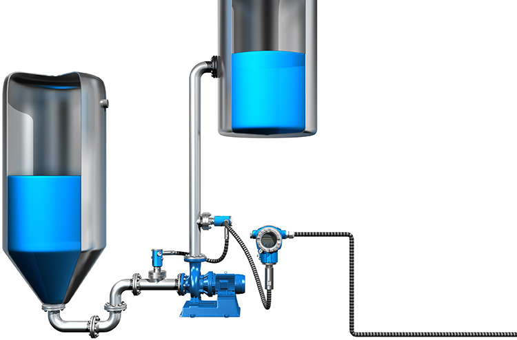
Image 1. An EdP transmitter monitors a pump’s suction and discharge pressure.

An EdP transmitter primarily measures level and differential pressure in tanks, distillation columns or cooling towers, but it can also be used in pumping systems (see Image 1).

An EdP transmitter can monitor the suction and discharge pressure (the differential pressure) of a pump. Too high or too low suction and discharge pressures can cause various pump issues such as cavitation, loss of flow, mechanical failure, vibration issues, excessive noise, and bearing and sealing wear.

The EdP transmitter outputs values for suction, discharge and differential pressure, and other useful values. An EdP transmitter can also monitor absolute pressure at each of the two sensing points.

High and low alarms can be set for any of the monitored values. The EdP has a 4-20mA HART output for connection to an automation system, such as a programmable logic controller (PLC) or a distributed control system (DCS).

The DP or gauge value from the EdP can be used to set alarms, which in turn help monitor problems such as cavitation.

For example, cavitation occurs if the pressure falls below a liquid’s vapor pressure in the impeller or if air entrainment occurs. Monitoring the discharge pressure and comparing it to a table of correct pressures at the automation system will reveal cavitation. Monitoring pressure in the suction line can indicate problems such as leaks or a clogged valve or strainer. If suction pressure drops below preset limits, the EdP transmitter will send an alarm.

Setting the Right Flow Rate

Incorrect flow rate settings are one of the typical causes of inefficient pump operation. Following is an example of how to use the EdP to set the right flow rate. For a given pump curve, first note:

Pump curve for determining flow rate of a pump
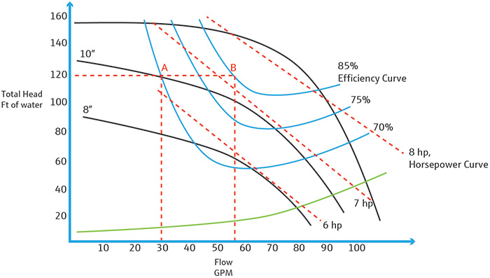
Figure 2. Pump curve for determining flow rate of a pump with a 10-inch impeller.
  • impeller size
  • rated horsepower
  • impeller speed
  • expected flow at BEP

The pump curve is typically provided by the manufacturer (see Figure 2). Run the pump with media flowing through the system at an arbitrary flow. Let the flow stabilize. Note the reported differential pressure. This is the total head or differential pressure of the pump.

Assuming 120 feet of water is the total head generated by this 7 horsepower (HP) pump, point A is the intersection with the 70 percent performance curve. The corresponding value on the X-axis (30 gpm) is the flow rate for the pump at an efficiency of 70 percent, corresponding to a net positive suction head (NPSHr) of 10 feet of water.

Pump curve for monitoring total head.
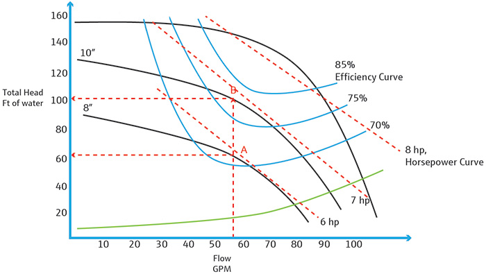
Figure 3. Pump curve for monitoring total head.

To increase efficiency and run this pump at the same total head, the flow rate needs to be increased to 55 gpm (right-most red dotted line in Figure 3) so that the intersection with the 85 percent efficiency curve will be at point B. The users should set high and low alarms on the EdP output to keep the DP tightly controlled while increasing the flow rate.

If the pump doesn’t generate 120 feet total head at the 55 gpm flow rate, this could be your first indication of an operational or mechanical issue. Check the suction pressure and ensure it is greater than NPSHr. Check the discharge pressure and calculate the HP generated and verify it matches the listed HP on the pump curve for the operating flow rate.

Monitoring Total Head

Assume 55 gpm is the operating flow rate for a 6 HP pump with an 8-inch impeller. The expected intersection on the performance curve for this pump would be point A (see Figure 3). The corresponding expected total head on the Y-axis would be 65 feet.

EDP pictureImage 2. An EdP differential pressure transmitter mounted across a pump.

The EdP transmitter sends its outputs to an automation system that has control logic and calculations to convert the transmitter data to total head. The automation system compares the EdP transmitter outputs to the expected total head—65 feet of water in this case—and adjusts pump speed accordingly.

This alters the pump speed to maintain the pump at BEP, which is 70 percent according to the manufacturer’s pump curve.

If higher pump efficiency is desired, the pump must be run at a higher speed, or a larger impeller diameter needs to be used.

With a known flow rate, different impeller sizes can be used to arrive at a desired total head and corresponding efficiency. Referring to Figure 3, if 55 gpm is the known flow rate, then an 8-inch impeller can be used to achieve 70 percent efficiency. If a higher efficiency is desired, then a 10-inch impeller can be used to achieve an efficiency of 75 percent, and a 12-inch impeller would achieve 85 percent. The corresponding total head would then be 100 feet of water.

Increasing efficiency from 70 to 75 percent on five pumps
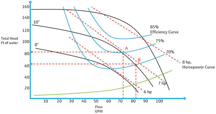
Figure 4. Increasing efficiency from 70 to 75 percent on five pumps can save over $12,000 per year.

Return on Investment

An EdP transmitter can pay for itself in a matter of months. Let’s use an example of a pump in a large industrial chemical company (see Figure 4). The company spends approximately $1,000 per year for seal failure and replacement because it operates its pumps below the BEP.

Point A represents the BEP of a 7-HP pump with a 10-inch impeller operating at 75 percent efficiency. If the pump is in continuous operation, the energy consumption per year would be $1,310 at 10 cents per kilowatt-hour (kWh). Point B represents the deviation from optimum, operating at only 70 percent efficiency.

The total cost of operating the pump at 70 percent efficiency is $2,151, where lost power output per year is $1,151 and repairs due to seal failure, vibration issues, other cavitation damages and associated downtime are $1,000. Total cost, considering a system of five pumps, is more than $12,000 per year.

The average cost of an EdP transmitter is $4,000. If the efficiency of the pumps is increased to 75 percent, using the techniques described in this article, annual savings amount to about $8,000 per year or $667 per month, providing a return on investment in about six months.