

Sponsored Content
As the world is accelerating toward decarbonization and adapting to energy transition, the oil and gas industry has a critical role to play, from downstream petrochemical and refineries to midstream gas processing and transportation facilities to upstream exploration and production (E&P) companies.
One common challenge across the oil and gas industry is methane and carbon emissions from flaring. Approximately 150 billion cubic meters of natural gas is flared every year. This results in emissions of roughly 300 million tons of carbon dioxide (CO2), not to mention the methane emissions from uncombusted portions of flares. While mandatory government policies have been tightened, there is an increasing number of voluntary government and industry commitments to reduce flaring, methane emissions and improve carbon footprints.
Here are five key facts users should know about flaring.
- The flare stack is an open gas combustion device used at industrial sites to burn off waste gas or for emergency pressure relief.
- A flare stack produces fire as part of controlled burning taking place for a few typical reasons: as part of testing to stabilize pressure and flow from a well; managing waste gas that can not be captured or processed; and for safety or emergency situations to release pressure. Flare stacks are mostly found in refineries, chemical and petrochemical plants, natural gas processing plants, offshore exploration platforms, well heads and landfills.
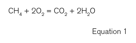
- The flare stack’s main purpose is to combust vent gas, a large portion of which is methane. When methane—or CH4—is burned, it produces CO2 and water (H2O). If the methane is not burned, it will be released into the atmosphere as is. The methane is invisible, or the flare exhaust looks like steam (for downstream steam-assisted flares). Methane is 84 times more damaging to the environment than carbon dioxide when it comes to warming the planet over a 20-year period. Operators need to have flare stacks optimized for combustion efficiency, so as much methane as possible is burned, converting it fully into carbon dioxide and minimizing a facility’s long-term carbon dioxide equivalent emissions.
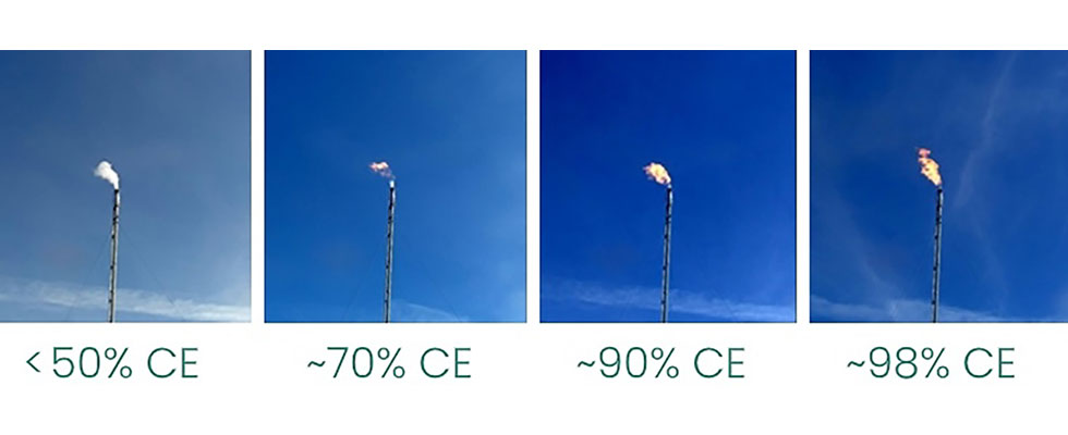
- People see fire and automatically think it is dangerous, but the reality is, if someone sees a flare stack venting methane masked with steam, that is far worse. The bigger and brighter the flame, the less of an impact that facility is having on the environment, from a carbon-emissions standpoint.
- Companies can reduce routine flaring by finding uses for the gas instead of burning it. Capturing this gas through a so-called flare gas recovery system gives operators an opportunity to produce more energy. While flare gas recovery is impactful, it can be costly and is not practical for certain operators, including flare operators located in remote areas.
A Flare Control Solution
A new solution can help facilities operate at 98% efficiency or higher and cut up to 12,100 metric tons of CO2 equivalent emissions per flare annually. For example, at a facility operating at 70% flare efficiency, the use of this technology will deliver 98% + efficiency—or the equivalent of removing 34,0001 cars from the roads. For operators, they addressing carbon footprint targets, but they can also save costs. Deploying this technology at a facility with 70% flare efficiency will save an estimated $5 million2 per year. The impact is better for facilities operating flares at less than 70% efficiency.
How It Works
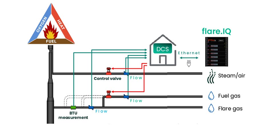
The flare control system can work for air- or steam-assisted flares, depicted in Image 2. The system is connected to the operator’s DCS through Modbus TCP/IP. It will pull critical information about the operator’s flare system, including vent gas flow, pressure, temperature, sound speed, gas composition, etc. It will then use patented algorithms to calculate the optimum usage of fuel and steam in real-time. This ensures benefits: no black smoke due to soot formation—global regulation does not allow for black smoke; required net heating value (NHV) in the combustion zone to gain high-combustion efficiency to reduce methane emissions and carbon footprint; and minimum steam/air and fuel usage to minimize operational cost.
Other System Benefits
The technology reduces methane emissions, ensures high-efficiency flare combustion and reduces steam usage, and it helps users manage assets remotely.
The system collects a wide range of data including vent gas flow, composition, pressure and temperature, which are processed to digitally verify ultrasonic flare meters. The technology helps improve safety and efficiency across the industry.
- Facilities no longer require manual verification of flare meters. Therefore, the logistical and operational cost of technician support, scaffolding and permit application is eliminated.
- The construction of scaffolding and the associated manual verification of flares is a safety risk. This technology can eliminate that risk.
- Manual verification can often interrupt plant operations while the flare meter is checked, but downtime is avoided with this control system.
- Having access to real time combustion efficiency data on the production floor enables plant operators to identify issues and address them promptly.
Prior to this control system, users would typically inject assist gas—such as steam—to the flare tip to control the combustion according to visual judgments. With the system, this process is automated.
For refiners and petrochemical facilities in the U.S., the technology helps to meet the requirements of the U.S. Environmental Protection Agency’s Maximum Achievable Control Technology (MACT) Petroleum Refinery Sector Rule (RSR) Part 63.670.
References
- Assumes 500k barrels per day refined, potential savings based on real use cases.
- CO2 at $23 per metric ton, Methane at $10 per 1,000 standard cubic foot, CO2 eq (methane) = 25x. Potential cost savings are estimated and not guaranteed and may vary depending on the application.
