

Inspired by recent events, I hope to clear up the continual confusion around net positive suction head (NPSH), specifically as it pertains to self-priming pumps on a lift application.
Yes, I have written numerous articles on NPSH, and I predict there will be many more after this one. There are two areas I wish to address this month. First, we will look at why the tedious and elusive game of obtaining adequate NPSH can look like a game of whack-a-mole, trying to skirt the laws of physics. Secondly, some insight into the negative effects of a prolonged system “priming time” and why you do not want a pump suction line that is too big or too long.
First Things First
The column will focus on NPSH available (NPSHa). Before we proceed, it is important to review and understand the equation/formula for the calculation of NPSHa in a suction lift situation. As I tell my students, “The formula is your friend.”
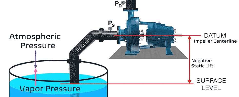
For simplicity, we will examine systems that are open to atmospheric pressure and assume the liquid is water. The simple definition for a system in a lift condition is that the upper level (surface) of the liquid to be pumped is at a level below the centerline of the pump impeller.
If you are uncomfortable working the formula or are confused on how to determine and fill in the factors for your specific situation, I suggest you review my previous articles on this subject, especially July and August of 2018.
Equation 1
NPSHa = habs – hvpa – hstatic – hfriction
Where:
habs = Absolute pressure head = A
hvpa = Vapor pressure head = V
hstatic = Static suction lift = S
hfriction = Friction head = F
Simplification
For simplicity, I have renamed the four factors in Equation 1 as A, V, S and F (see Equation 1 for a definition of the assigned terms). The simplified formula can now be expressed in Equation 2 as:
NPSHa = A - V - S - F
Note that A is always positive and will normally be less than 33 feet and the other three factors are all negative terms. Notice that if the three negative factors add up to be any number even close to 33, you will have no NPSHa.
As a paradigm shift, let’s turn things around a little from how we typically conduct the calculation. Normally we determine the four factors in the equation and calculate to find the value of NPSHa. Typically in the field, we already know the NPSH required (NPSHr) for the pump. Further, we would also determine how much additional head we require/desire above the NPSHr for a reasonable NPSH safety margin.
Next, I suggest that we take the NPSHr value from the pump, add the desired NPSH margin and set that total on one side of the equation as equal to the four unknowns on the other side of the equation/formula.
For example, if the pump required 10 feet of NPSH and we wanted a 5-foot margin, then the NPSHr needs to be at least 15 feet rather than 10 feet. We will designate this new factor as NPSH desired or NPSHd. NPSHd in this example is the sum of NPSHr (10 feet) and the margin (5 feet) for the 15 feet of NPSH desired.
The previous formula would now look like this in Equation 3:
NPSHd = A - V - S - F
Perhaps A - V - S - F ≥ 15 feet may be the better way to think of the equation because 15 feet is the desired minimum and more is acceptable. The absolute sum of the four factors (A, V, S, F) in the equation must total 15 feet or higher for the pump application to work correctly (satisfy the equation).
Next, we will examine each of the four factors one at a time to examine possible outcomes.
Absolute Pressure Head (A)
The A term is based on absolute pressure exerted by the atmosphere. We already stated that the system was open to atmosphere but we didn’t state the site elevation above sea level.
For ease of working the problem, assume we are close to sea level and round down the normal sea level value of 33.9 feet (absolute) to 33 feet (14.7 pounds per square inch [psi] x 2.31 = 33.9 feet). I like to be conservative in these calculations, so this is the reason why I rounded down.
The three remaining terms (V, S, F) are all negative and their sum total will be subtracted from the A term (33 feet), we can also reason that the sum of the three remaining terms must be ≤18 feet or the pump will not work properly. Assume the absolute total of the three terms is X and solve for X (Equation 4).
(33 - X = 15) solve for X yields
33 - 18 = 15
Equation 4
From this step, you can surmise that the total (absolute) values of V, S and F must be less than 18 feet.
Lift or (Negative) Static Head (S)
For the next step in the example, we will establish the negative static head (the lift) as 8 feet. Note that this term is an actual measurement, not a calculation. Consequently, the S term in our simplified Equation 5 now has a value of 8 feet. If S is 8 feet, then the sum of friction F and vapor pressure V total must be less than 10 feet.
18 = V + S + F
S was measured at 8 feet, so:
18 = V + 8 + F
therefore: 10 = V + F
Equation 5
We need to view this as 10 ≤ V + F, where we are expressing the terms in their absolute values and not the negative terms from the formula. You can look at this mathematically, but I think it is more important to look at it as you have limits on how much friction and vapor pressure can be present. If the value is exceeded, the pump will not operate properly or at all.
Friction Factor (F)
Before we address the vapor pressure, I want to skip ahead to the friction factor F. The total friction head was calculated at 3.86 feet, but to be conservative and to also allow for “aging” of the system, we will round off to 4 feet of friction head. Now we have a value of 4 feet to assign to the F term in the equation. From this, we can calculate that we now have 6 feet of possible margin before we calculate the value of the vapor pressure term (Equation 6).
10 = V + 4, or V = 6, and again we should think of this as V ≤ 6
Equation 6
Vapor Pressure (V)
Vapor pressure in the US-C system is normally expressed in pounds per square inch absolute (psia), consequently you will need to convert to head ([psi X 2.31] ÷ [specific gravity] = head of vapor pressure absolute).
The V term (vapor pressure) seems to be an almost insignificant factor for liquid temperatures near ambient, which can be misleading and lure you into the false sense that it is not important. For a more detailed explanation of vapor pressure, please refer to my detailed column in the April 2018 issue.
Realize that as the liquid temperature increases, so does the vapor pressure (V) and it does so at an exponential rate. At around 68 F, the value of V would only be 0.78 feet absolute, but at 90 F it would increase to 1.62 feet absolute and at 160 F, it would be 11.21 feet absolute, and at 200 F it would be 27.65 feet absolute. Hint: this is the main reason you will not see a self-primer on applications (with a static lift) at liquid temperatures over 145 F. You do not need to calculate the value of vapor pressure, you simply look it up in a handy-dandy trusted chart. I like to use the “Cameron Hydraulic Data” book.
For our example, let’s assume the water is 80 F and so the corresponding V will be 1.1745 feet absolute, which I will round off to 1.2 feet absolute.
With this value of 1.2 feet for the vapor pressure, we can finalize/satisfy our equation (Equation 7).
V ≤ 6? Yes, 1.2 is less than 6.
Equation 7
We can surmise that this application will work and we even have an extra margin of 4 feet.
Priming Time—Don’t Wait Too Long
In the previous example, the water was near ambient temperature and the pump was close to the sump (suction source) with a properly sized suction pipe. I recently witnessed performance issues with two separate installations where the pumps were placed a long distance from the sump, and in one instance the suction pipe was several sizes bigger than it needed to be.
The larger pipe size reduces the friction factor but significantly increases the air volume to be removed. Both factors (pipe length and diameter) increase the air volume and require the pump to “work” harder and spend more time in the air removal process.
During the priming process, the water in the priming cavity/chamber is being recirculated and churned by the impeller. This shearing action adds heat and increases the liquid temperature rather quickly. It is difficult to accurately calculate how fast the liquid temperature will rise for your installation as there are many factors involved but note that the amount of brake horsepower and speed are two major factors. Be aware that 3,550 rotations per minute (rpm) units will heat the liquid about eight to 10 times faster than 1,750 rpm units.
It is not uncommon for the liquid in the chamber on the higher-speed pumps to heat up at the rate of 40 to 50 degrees a minute. Some of that heat will be dissipated to ambient, but my point is that the liquid does heat rather quickly and that changes the vapor pressure. As the temperature and vapor pressure increase, the risk/probability of flashing the liquid in the priming chamber also increases. Additionally, the liquid surrounding the mechanical seal will also heat up and flash to vapor (not all mechanical seals are subjected to this seal chamber situation and it depends on the manufacturer, model and design).
In any open system with a self-priming pump lift application, vapor pressure, friction and static lift are not your friends. You do not have an infinite amount of available positive energy to combat them. Your only friend is absolute pressure. Design the system to have short priming times by placing the pump near the source and size the suction pipe properly.
Additional Notes
- Equation 1 is valid for a suction lift condition. If the system was in a flooded condition, the static head term would be positive.
- Only consider the suction side of the system in a NPSHa calculation.
- All the factors in the formula must be expressed as absolute values.
- All factors need to be consistent. That is, they should either all be in U.S. customary units of feet or units of meters for metric calculations.
- Since we are dealing with a static head that is negative, it is designated as a “lift” situation.
- Calculate the system NPSHa for the worst-case lift/scenario. What is the lowest liquid level that will be experienced?
- Remember that the critical submergence must also be calculated. Pump performance can easily be diminished by air entrainment.
- The head due to vapor pressure is a direct function of the liquid temperature and is always a negative term.
- The head due to friction is always a negative term.
- The head from absolute pressure is, in essence, the atmospheric/barometric pressure and must be corrected for the site elevation above sea level.
- The absolute pressure (head) can theoretically be as low as zero but it cannot be a negative term. Since we are working with an open system in a lift condition, it is unlikely that the absolute pressure would ever be less than 12 feet.
