

The average water consumption in United States pulp and paper mills is approximately 17,000 gallons/ton, with the most efficient kraft pulp and paper mills consuming as little as 4,500 gallons/ton. The primary driver for water consumption is the need to pump the pulp and its byproducts throughout the various stages of the paper producing process. The fibrous nature of the process fluid can wreak havoc on the operating temperature and cleanliness of the mill’s rotating equipment’s sealing devices.
As the industry continues its focus on reducing its impacts to the environment by consuming fewer natural resources and energy, the pulp and paper industry has focused on reducing water consumption. For the pulp and paper industry, the operation of sealing devices is a large contributor to both water consumption in terms of flushing the sealing device continuously with clean fresh water, as well as energy consumption. When one considers that the water flushed into the sealing device and process stream must ultimately be removed again through an evaporation process, a large amount of energy in the form of heat is also consumed.
The two most common sealing devices employed in rotating equipment in the pulp and paper industry are mechanical seals and gland packing. Gland packing, by the nature of operation, requires a continuous stream of water to be applied to it via a flush port located in the equipment’s stuffing box. This water flush should be relatively clean and available at a continuous pressure 15 to 25 pounds per square inch (psi) (1 to 1.7 bar) higher than the stuffing box with a flow rate of around 1 gallon per minute (gpm) (3.8 liters per minute [lpm]) depending on the size of the equipment. In a continuous process this equates to 500,000 gallons per year, per piece of equipment. In many cases, the flow of the water is somewhat unrestricted and unmanaged, leading to much higher consumption rates than needed.
For mechanical seals where a single mechanical seal is employed, the water consumption rates are often similar to that of pump packing as the requirement to keep the sealing device cool and clean remains. Older equipment is often upgraded from packing to mechanical seals to achieve electrical energy efficiency gains, as well as improving the working area by eliminating the atmospheric leakage associated with packing. Alongside the energy efficiency and environmental improvement gains, mechanical seals offer improvements to the equipment operating costs, as there will no longer be damage to the equipment shaft or sleeve.
Image 1 illustrates a typical operating plan for a single mechanical seal installed in a centrifugal pump with fluids containing solids or fibrous particles. The presence of the restriction bushing is not always recommended in fibrous fluids, and in some pump designs the seal chamber diameter can be large and tapered, preventing the use of a restriction bushing. To reduce product dilution and reduce the energy consumed in the evaporation process, some users have migrated from single mechanical seals to double mechanical seals. The need for water to cool and clean the sealing device remains; however, in a double mechanical seal, little water enters the process stream. The volume would be measured in fluid ounces/day as opposed to gpm. The seal’s water flush is often piped to the inlet port of the seal, while the outlet port of the seal is piped to run to drain. In doing so, the volume of water consumed per equipment remains similar for pump packing or a single mechanical seal. Common practices are to employ valves on the drain side of the pipework to provide restriction in flow and pressure to the inboard and outboard seal faces.
.jpg)
IMAGE 1: Mechanically sealed pump with static shaft sleeve/sealing surface
Just like flushing pump packing or single mechanical seals, double mechanical seals operate best when the flush water is applied at a pressure 15 to 25 psi (1 to 1.7 bar) higher than the seal chamber pressure. By having a positive pressure margin above the seal chamber pressure, the process fluid is unable to contaminate the mechanical seal faces and only a small but steady amount of flush water migrates across the faces into the process. Using a reliable pressurized water source is important, as premature seal failure of a dual mechanical seal can often be attributed to variable water pressure and flow from the water header due to other process demands upstream of the seal water connection.
Operating double mechanical seals in this way improves product quality and reduces the energy consumed to evaporate the water introduced from the sealing devices flush out of the process in the next stages of the manufacturing process. This sealing flush method can be improved further to increase seal life and reduce water consumption.
Image 2 illustrates a typical American Petroleum Institute (API) Plan 53A pressurized barrier system, which mechanical seal manufacturers may modify to create water fed closed loop barrier systems. By using a water fed barrier tank system with a double mechanical seal, often called a closed-loop barrier system, the mechanical seal is able to receive the cool, clean water needed to operate correctly without sending large amounts of water to the drain. For double mechanical seals with a closed-loop barrier system, the only water lost from the system is the water that crosses the inboard and outboard seal faces, a few fl. oz. per day.
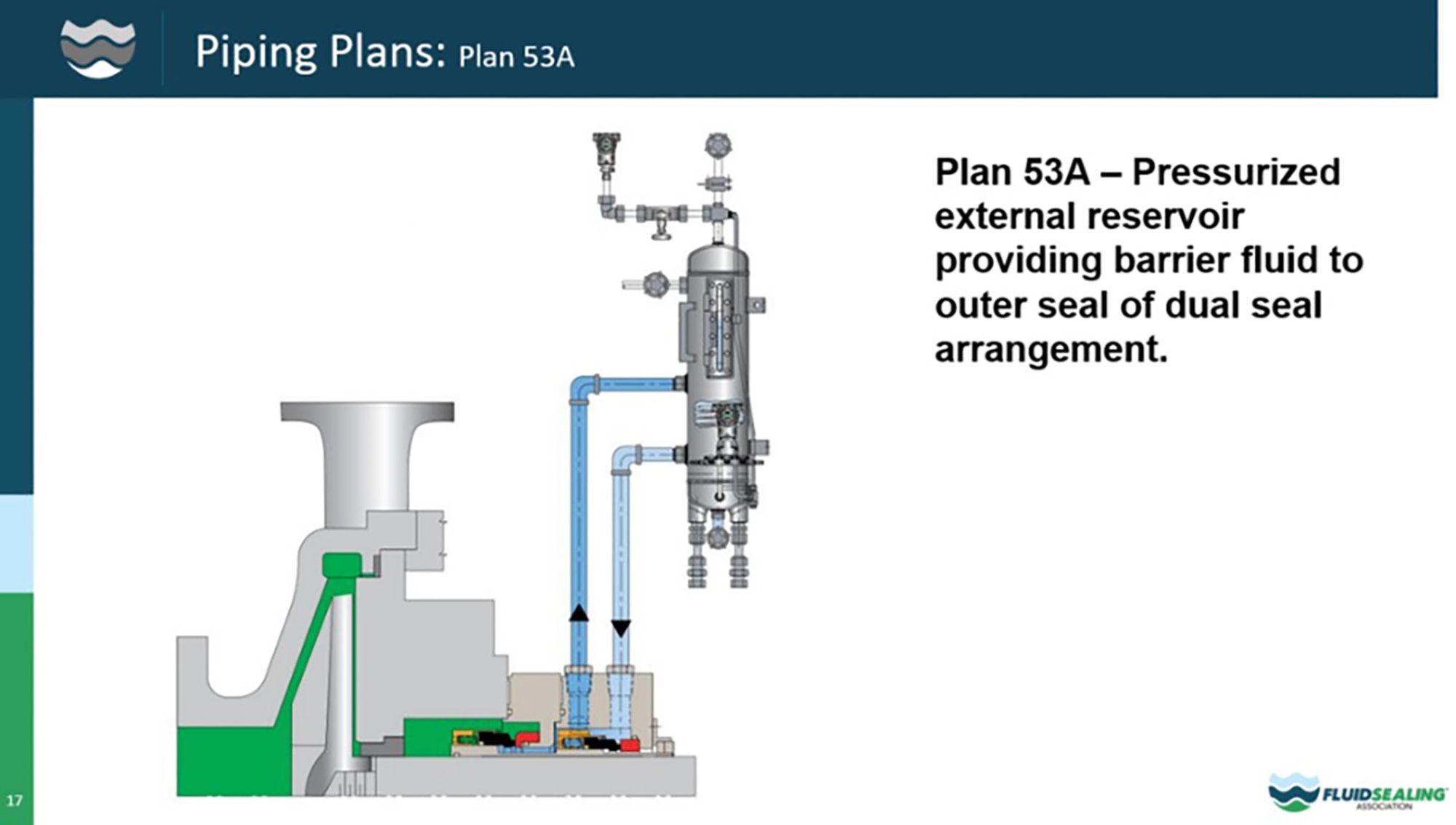
IMAGE 2: Double mechanical seal with liquid barrier reservoir pressurized from flush header
This sealing solution virtually eliminates water usage to operate the seal and any water contaminating the process. Other benefits related to employing a correctly configured barrier system are isolation of seal performance from upstream upsets, ability to regulate the seal water at a set pressure, an ability to provide ongoing monitoring of the health of the mechanical seal and two seals that can operate as a single seal for a short period of time in the event of flush or seal failure.
No single sealing solution or seal flush option is perfect for every application within a pulp and paper plant. However, there are different sealing solution options currently in use that can reduce water and energy usage while providing reliable sealing of pulp and paper equipment. Work with your seal vendors when reviewing your plant’s resource reduction initiatives and see if a different sealing solution for your applications can help achieve your resource reduction goals.
We invite your suggestions for article topics as well as questions on sealing issues so we can better respond to the needs of the industry. Please direct your suggestions and questions to sealingsensequestions@fluidsealing.com.
