
Sealing Sense
02/01/2017
Editor's Note: This is the last in a series. Find other articles in this series here.
Many members of the Fluid Sealing Association (FSA) Non-Metallic Expansion Joints Division and of the Expansion Joint Manufacturers Association (EJMA) feel that expansion joints are the forgotten components of many piping systems. Other piping system components—flanges, gaskets, strainers, valves, pumps and the pipe itself—seem to get most of the design time.
In many ways, expansion joints are the most important components of a well-designed piping system. They are the “living and breathing” dynamic part of the whole system.
Without well-designed and well-placed expansion joints, parts such as pump nozzles, valve bodies and pipe anchors could face excessive loading and vibrational fatigue. Without proper compensation, thermal growth at elevated temperatures can damage some pipes, reducing their operating life.
Expansion joints are sometimes misunderstood. Despite the name, expansion joints normally do not expand during operation. They compress in most applications. Expansion joints provide stress relief from thermal and mechanical vibrations and/or movements in piping systems.
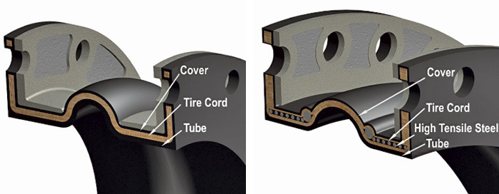 Figure 1. Typical expansion joint construction (Graphics courtesy of FSA)
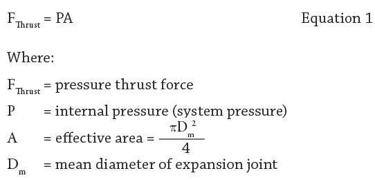 The pressure thrust force of an expansion joint is defined in Equation 1.
For example, a 12-inch internal diameter (ID) expansion joint could have a mean diameter of 13 inches. Calculating the effective area and multiplying by an internal pressure rating of 100 pounds per square inch gauge (psig) would result in 13,273 pounds of thrust force. Without properly designed anchors, this force could cause the piping to move, leaving the expansion joint to counteract the forces.
Under axial deformation, the expansion joint spring rate also must be considered. In this example, a spring rate of 500 pounds per inch (lb/in) would not be uncommon.
For a compression of 1 inch, another 500 pounds of axial force must be added to the resultant forces on the anchors. These factors often are overlooked.
One important consideration when dealing with these types of movements is the use of control rods, which are essential pieces of hardware added to the expansion joint during installation.
Contrary to widespread belief, control rods are not designed to keep the expansion joint in line and prevent the joint from moving in excessive lateral offset. They are designed to limit the amount of movement the expansion joint is exposed to during operation.
These movements can result from large forces, so the joint and the control rods must be designed to withstand all stresses involved.
The pressure thrust force of an expansion joint is defined in Equation 1.
For example, a 12-inch internal diameter (ID) expansion joint could have a mean diameter of 13 inches. Calculating the effective area and multiplying by an internal pressure rating of 100 pounds per square inch gauge (psig) would result in 13,273 pounds of thrust force. Without properly designed anchors, this force could cause the piping to move, leaving the expansion joint to counteract the forces.
Under axial deformation, the expansion joint spring rate also must be considered. In this example, a spring rate of 500 pounds per inch (lb/in) would not be uncommon.
For a compression of 1 inch, another 500 pounds of axial force must be added to the resultant forces on the anchors. These factors often are overlooked.
One important consideration when dealing with these types of movements is the use of control rods, which are essential pieces of hardware added to the expansion joint during installation.
Contrary to widespread belief, control rods are not designed to keep the expansion joint in line and prevent the joint from moving in excessive lateral offset. They are designed to limit the amount of movement the expansion joint is exposed to during operation.
These movements can result from large forces, so the joint and the control rods must be designed to withstand all stresses involved.
Non-Metallic Expansion Joints
Non-metallic expansion joints typically consist of three layers: the tube, body and cover. The tube is a leak-proof protective inner liner made of synthetic or natural rubber. It extends seamlessly through the ID of the expansion joint from outside flange to outside flange. The cover is the exterior surface of the expansion joint, and it is made of synthetic or natural rubber. It is designed to protect the inner portions of the expansion joint from external conditions. The body—or “carcass” as it is sometimes called—is the internal reinforcement encapsulated by the tube and cover. The body provides the expansion joint’s structural strength under varying system pressures and vacuum conditions. The body can have two types of reinforcement: fabric reinforcement consisting of quality synthetic fabrics and metal reinforcement in the form of wire or solid steel rings. All layers contribute to the overall strength and protection of the expansion joint while maintaining flexibility. Non-metallic expansion joints are superior to metallic joints in most chemical applications. Elastomers are generally more resistant to acids, solvents and oils than metallic joints. In corrosive chemical applications, high-priced exotic materials such as Inconel, Hastelloy or Carpenter 20 might be required for metallic joints. Polytetrafluoroethylene (PTFE) is resistant to nearly all chemicals but hydrofluoric acid. In many applications, elastomeric expansion joint spring rates are lower than those of metallic joints, especially for higher-pressure applications. Non-metallic joints can handle some higher-pressure conditions better than metallic joints. Lower spring rates are critical in new PVC piping systems where the pipe is weaker than standard metallic pipe. Using non-metallic softer expansion joints can result in lower pipe and anchors loads, so PVC pipe will be less likely to fail. Metallic expansion joints have restrictions in terms of life cycle. It is necessary to know how many cycles a joint can move the predicted movement. Certain programs can be used to predict when fatigue metal fracture is expected to occur. Non-metallic expansion joints, on the other hand, are not limited by cycling fatigue. In general, non-metallic joints can withstand axial compression and lateral offset movement combinations better than metallic expansion joints because material fatigue is not a factor. Non-metallic joints are also superior to metallic joints when used to absorb vibration. They possess inherent damping capabilities. Metallic joints typically fall short of acceptable life when dealing with high-amplitude and high-frequency vibrations. Elastomeric expansion joints are ideal for pump suction and discharge applications because of their ability to absorb axial and lateral movements along with vibration.Selection & Specification
When choosing the correct expansion joint for a given application, end users must know the accurate design conditions of the area where the expansion joint will be installed. Experts agree that many non-metallic expansion joint failures result from incorrect information or lack of information.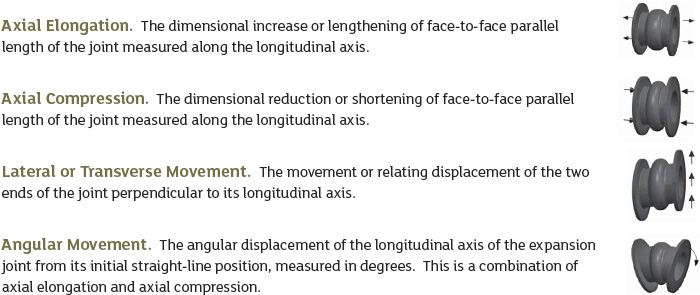 Figure 2. Axial extension and compression (in inches), lateral or parallel movements (in inches), and angular movements (in degrees).
See other Sealing Sense articles here.
Expansion Joints
For more information about expansion joints, visit the FSA product locator at fluidsealing.com/product-locator, or contact a manufacturer.
