Externally pressurized porous gas bearings are being applied in seal applications for rotating equipment.
New-Seal Inc.

By leveraging the pressures that can be generated in the gaps of externally pressurized porous (EPP) gas bearings, a new class of seal offers capabilities not previously available.

EPP gas bearings have been used in other industries for decades, but they are now being applied in seal applications for rotating equipment. This technology should increase the pressures that can be sealed against; reduce the flow of buffer, barrier and seal gases; and eliminate friction, heat and wear in seal applications.

There are two types of gas bearings: aerodynamic and aerostatic. Most large pump and turbine rotors are supported on hydrodynamic oil bearings. Dry gas seals in compressors are examples of aerodynamic technology, and many micro-turbines are supported on foil-type aerodynamic bearings, while pump seals are often riding on a self-generating film.

EPP Gas Seal FaceImage 1. Air bubbles emerge from an EPP gas seal face. (Images and graphics courtesy of New-Seal Inc.)

In these cases, the relative motion between the surfaces draws the fluid or gas into the gaps. Motion is required to generate separation force, and there will be contact wear at start-up, shutdown and in slow speed conditions.

In static-type bearings, motion is not required to generate separation force between the faces. Instead, a source of externally pressurized fluid or gas is injected directly between the bearing or seal faces. This pressurized flow of fluid or gas is introduced though the faces via precise orifices, grooves, steps or porous compensation techniques.

This idea of compensation is important but not widely used in the rotating equipment industries.

Compensation is the first restriction. It holds source pressure in reserve. This enables the faces to run close without touching because as they get closer, the gas pressure increases between them.

This is because the gap is the second restriction, and as it is reduced (increasing the gap restriction) the compensation restriction is relatively less, so pressure in the gap increases and creates a separating force. The gas pressure in the gap can be almost as high as the source pressure because the small gap is restrictive.

With flow being a cubed function of the gap, gas consumption is dramatically reduced by the small gaps that become possible.

Compensation Method

One method for providing compensation is to diffuse the seal gas though a porous material. The ideal seal design would supply pressure equally across the whole seal face and automatically restrict and dampen air flow to the face. The stability of porous media compensation is due to the damping effect from the passageways the gas must flow through to reach the face. This damping effect makes it difficult for the volume of air in the gap to change quickly, resulting in a naturally stable gas film that cannot be plugged by particulates.

Double-Opposed EPP Gas Seal
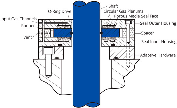
Figure 1. This diagram shows a double-opposed externally pressurized porous (EPP) gas seal.

Even if the supply tubes and/or ports become full of particulates (sand, dust, Teflon tape, etc.), this debris does not create as much restriction as the porous media itself, and none of these contaminants can get though the porous media and into the seal gap. These characteristics make EPP compensation a good choice for seal applications. The porous media is made from materials such as graphite, carbon or silicon carbide that have proven their plain bearing tribology as contact seal faces, bearings and brushes over decades of use in rotating equipment. Even if the source pressure is lost, there is little to no wear and small gaps are maintained.

These materials have high heat capability, a result of being sintered during manufacturing; they resist oxidation to at least 600 C without melting like Babbitt or burning like polymers. Although the O-ring drive for the runner is convenient, runners may be hard-mounted to the rotating shaft, making it possible to apply the technology to high-temperature applications.

Work is under way on seals for steam turbines that would be comparable in flow to dry gas seals. The external pressure source is bled from the high-pressure steam before it enters the turbine. Seals this effective could dramatically reduce the axial length required for steam seals and the leakage rates typical of steam turbines.

Mounted double-opposed EPP gas seal with monitored vent
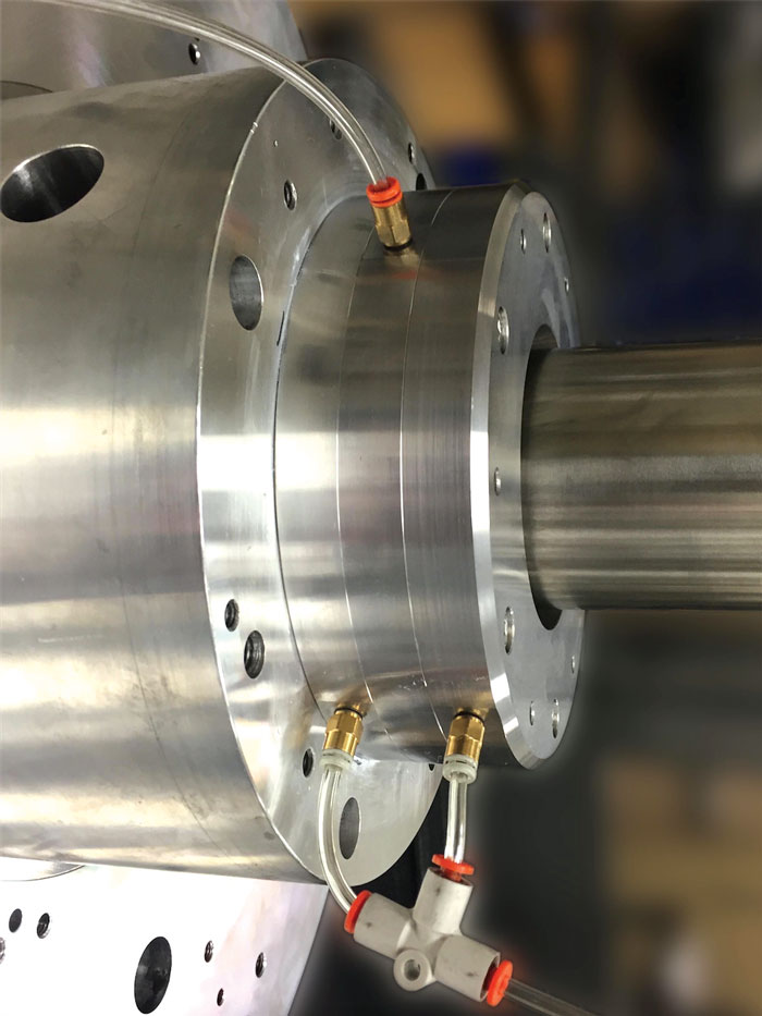
Image 2. Mounted double-opposed EPP gas seal with monitored vent

EPP gas bearing technology may be applied in many other seal applications. Examples of conventional seals that could be replaced with EPP gas seals include packing seals, labyrinth seals, steam seals, bearing isolators, injection-type seals, mechanical seals, dry gas seals and hydrogen seals. Because EPP gas bearing technology requires less space than most conventional seals and is offered in familiar mounting geometries, retrofitting with the technology can be fairly easy. The technology can be used in a variety of applications, such as oil-free turbo equipment, pumps, compressors, and steam and gas turbines.

A unique feature of the externally pressurized gas seal is the O-ring drive between the runner and the shaft. This allows for easy retrofit as the runner may be positioned anywhere axially on the shaft, accommodating thermal growth of the shaft. The O-ring also allows the runner to deal with static and dynamic angular misalignment.

This concept may seem like it would not be as robust as having a feature that locks the runner to the shaft. However, because the runner-seal face interface is frictionless, the O-ring drive only needs to overcome the runner’s inertia.

Even though there are hundreds of pounds of clamping force on the runner, this force is exerted though the air films and is frictionless.

This drive mechanism has undergone thousands of hours of testing and has been successfully used in sealing applications including light gases, powders, slurries and one pump application sealing acid.

As seen in Figure 1, the external pressure is injected into the inner and outer seal housings. These ports may be connected internally, allowing for a single supply or two separate gases to be used (one for each face). The input gas flow travels into the 360-degree gas plenum regions and migrates through the porous media into the gap between the porous media face and the runner. The flow from each seal face is split.

Gap Pressure Chart
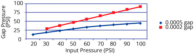
Figure 2. Gap pressure relative to starting gap clearance

On the inner side, there will be flow into the sealed cavity and the vent. On the outer side, flow will exit to the atmosphere and the vent.

As an example, using input pressure of 60 pounds per square inch gauge (psig), the gap pressure between the porous media face and the runner (assuming a 50 percent efficiency) would be approximately 30 psig. As long as this gap pressure is more than the sealed cavity pressure, there will be zero flow from the cavity into the seal gap.

A seal such as this for a 4-inch shaft will flow a total of about 0.5 standard cubic feet per minute (SCFM) for both faces. This efficiency is very sensitive to the gap; flow through a gap is a cubed function of the gap.

This is a key differentiator from more conventional seals because the small gaps allow for high gap pressures and low flows.

Seal Gap Diagram
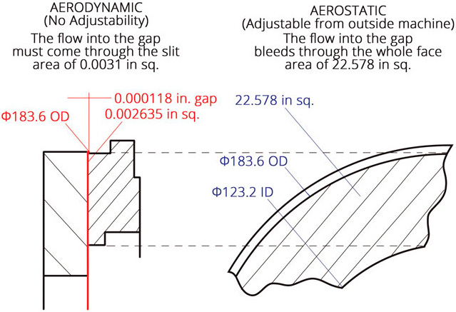
Figure 3. This diagram shows the area available for introducing gas into the seal gap.

In dry gas seals applications, externally pressurized sealing solutions may be performed with much higher pressures involved. Sealing against a 1,000 psi internal cavity pressure can be achieved as long as there is an adequate differential pressure across the porous media. In this case, an input pressure to the porous media would need to be about 1,060 psi to completely seal the 1,000 psi cavity pressure. At smaller gaps and higher pressures, efficiencies can be higher. It is necessary to keep the gap pressure higher than the pressure to be sealed.

This is another distinction between an EPP gas seal (an aerostatic seal) and a conventional aerodynamic seal, such as a dry gas seal or pump gas seal. The feed area for an externally pressurized gas seal is 4 orders of magnitude greater than that for an aerodynamic seal. This prevents choked flow and improves reliability. Controlling what gets in the seal gap improves reliability.

Issue