
Many vertical electric motors are used to drive water pumps. The selection of electric motors requires attention to many details including the power supply, environment and load. This article is an introduction to the effects of the load on the bearing system. Here, the bearing system refers to the core, housing, seals, method of lubrication and cooling.
Vertical motors are like horizontal ones with respect to electrical characteristics, but differ mechanically.
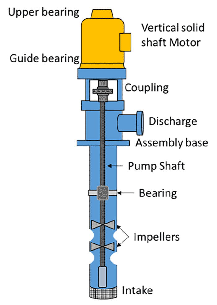 Image 1. The parts of a vertical motor assembled on a pump’s head (Images courtesy TMEIC)
Since they are assembled in a vertical position, the upper bearings alone support the weight of the rotors and, in some applications, the weight of the pump’s impeller, shaft and the hydrodynamic thrust.
Image 1 represents a vertical motor assembled directly on a pump’s head. Large and/or heavy motors can require a separate structure or foundation.
The upper bearing is expected to support the rotor and the external thrusts and, when specified, maintain radial stability, last a reasonable amount of time, require reasonable maintenance intervals and operate with reasonable losses. To design such a bearing system, the following parameters* are necessary:
- normal, continuous downthrust—the basis for calculation of bearing life
- maximum, momentary downthrust for tilted pad bearings
- minimum downthrust—needed for spherical roller bearings
- momentary upthrust—if continuous upthrust is predicted, the motor manufacturer should be informed
*[pound force (Lbf)] or [kilogram force (kGf)] or [kilonewton (kN)]
Many types of bearings are used on electric motors, according to the manufacturer’s standard. Large pump systems are likely to require custom bearing systems according to specifications. The most used types of bearing systems are the deep groove ball bearing, the angular contact ball, the spherical roller and the tilted pad sleeve bearing.
Types of Bearings & Use
Guide bearings—The guide bearing is at the lower part of the vertical motor, toward the shaft end. It provides stability to the rotor and can be used, when properly dimensioned, to sustain momentary axial upthrust.
Normally, a deep groove bearing is used with grease for lubrication. However, when the motor is fitted with a tilted pad type, the guide bearing is also a sleeve type.
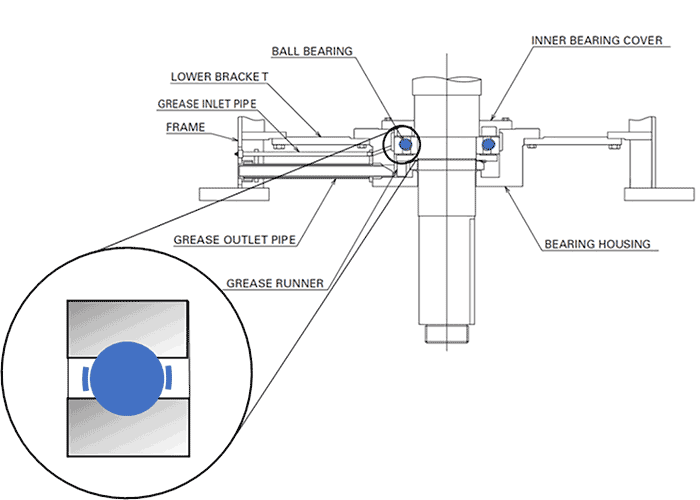
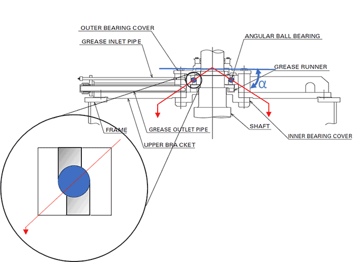 Image 2 (top). The assembly of a deep groove ball bearing on a motor. Image 3 (bottom). Angular contact ball bearing
Thrust bearings—A thrust bearing is installed on the upper part of the motor, opposite to the shaft end. Image 3 depicts an angular contact ball bearing type, which is typically used in smaller motor frames. The angular contact bearing can withstand forces in both radial and on axial directions due to the inner and outer raceways being shifted from each other with reference to the bearing axis.
The motor designer can select angular contact bearings with double rows of rolling elements to increase the downthrust capacity. The increase of the angular contact represented by the Greek letter α, between the rolling elements and the raceway, increases the load carrying capacity.
Grease can be used to efficiently lubricate this type of bearing in a wide range of speeds and downthrust values. When grease is no longer efficient, the bearing operates submerged in an oil reservoir. In larger frames, a serpentine with running water is installed inside the oil reservoir to maintain the temperatures as specified. The production facility must supply fresh water.
The spherical roller bearing (Image 4) supports large downthrusts. Its capacity to self-align compensates minor misalignment between the motor and the driven equipment without detriment to service life. The spherical roller bearings do not withstand thrust in the upward direction and must be loaded at all times to avoid losing radial stability. When momentary upthrusts are predicted, they are handled by a special configuration of the guide bearing.
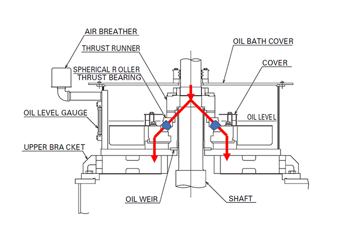
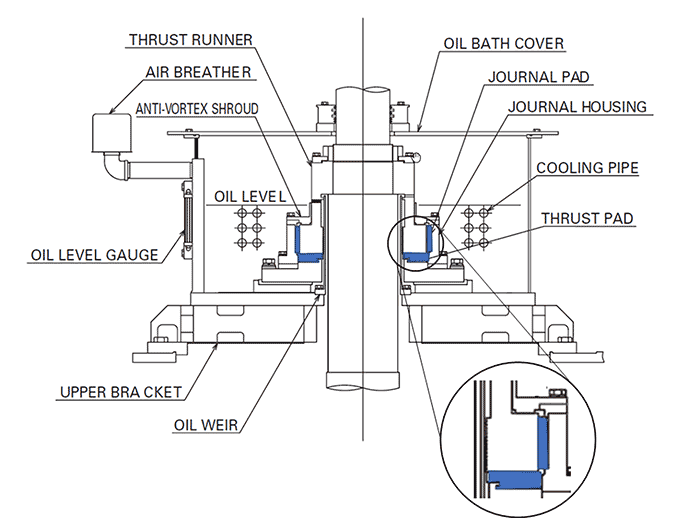 Image 4 (top). Spherical roller thrust bearing on an electric motor. Image 5 (bottom). Tilting pad thrust bearing on a vertical electric motor
Operation at this condition must be limited to avoid fatigue of the guide bearing.
To ensure that the roller bearing is always loaded, a set of springs is installed to push the lower race upward. When an upthrust occurs, the springs lift the lower race to maintain its contact with the rollers. In general, the load (hydraulic thrust) applied by a water pump decreases when the water flow increases, and increases when the water flow decreases.
When a variable frequency drive (VFD) powers the electric motor, it is possible to vary the speed of the pump to adjust the volume of pumped water while operating near the maximum efficiency of the pump system. The reduction of water flow unloads the bearing, and the springs will act to maintain the lower race in contact with the spherical rollers.
The lubricating oil of a spherical roller bearing can be air or water cooled to dissipate heat under heavy downthrusts.
The tilted pad bearing as shown in Image 5 includes two major parts: one series of metal pads, each pivoted at the center that allows them to incline (tilt), and a solid metal plate (collar) that, fixed on the motor shaft, runs over the pads. These parts are located in an oil reservoir and cooled by water, which is circulated through a serpentine pipe.
The rotational movement of the collar with the tilting movement of each pad allows the formation of a thin layer of oil between them. This layer of oil avoids contact between the two moving parts. Without the formation of the oil film, the friction heats the pads and collar, causing bearing failure.
When adequately lubricated, uncontaminated and not overloaded, a tilted pad bearing can last indefinitely.
Due to the large area of contact between the collar and the pads, the tilted pad bearing can withstand large downthrusts. For this durability and high capacity, the tilted pad bearings cost more than the ball or roller types.
Particular attention must be paid to conditions of operation:
- During startup, the bearing withstands the dead weight of the pump parts, which must be provided to the motor manufacturer, so it can be determined if the bearing requires a shaft lifting device.
- The acceleration of the motor must be rapid enough to establish the oil film between the pads and the collar.
- For the same reason, the maximum total downthrust predicted to occur at shutoff must be disclosed to the motor manufacturer.
- Pumps with an initial head at zero speed-loads the bearing before it can establish an adequate oil film.
- The lowest speed of operation must enable the formation of the oil film.
- A large overload can destroy the oil film. Therefore, any possibility of overload must be disclosed to the designer, and later, the rating of the motor-pump must not be exceeded.
Conclusion
The actual thrust values must be considered for proper selection of a bearing system. Avoid inflating the values as a means of obtaining a longer life or adding a margin “to be safe.” Longer life can be achieved by design based on the actual operating conditions.
When adding a VFD, it is not unusual to consider the motor insulation while missing the bearing. This is perhaps because operating a lower speed can benefit the bearing. However, at lower flows, the hydrodynamic thrust can diminish beyond the minimum thrust for a spherical roller-type bearing to function well.
All types of bearings require proper maintenance, cleanliness and the proper load so they can operate as designed. On upgrades or new pump systems, a collaborative relationship between the motor manufacturer and the pump OEM can result in superior pump systems.
When not informed by the user, a motor manufacturer may disclose the limits of maximum momentary downthrust up to 30 seconds—equal to 1.5 times the continuous downthrust. The momentary upthrust, up to 30 seconds, is equivalent to 30 percent of the continuous downthrust. While this can assist in not exceeding the bearings’ capacity, equipment owners should confirm that the motor matches the actual requirements of the pump and the operating conditions.
