

Centrifugal pumps are among the most commonly used devices for transferring fluids in industrial applications. Although quite rugged by design, centrifugal pumps typically suffer mechanical failure due to excessive seal wear, skidding damage in the bearings and/or bearing cage failure. This article explores these three failure modes and, using proprietary bearing calculation software, explains how proper bearing axial clearance can mitigate these problems to extend the service life of the bearings and, ultimately, the pump itself.
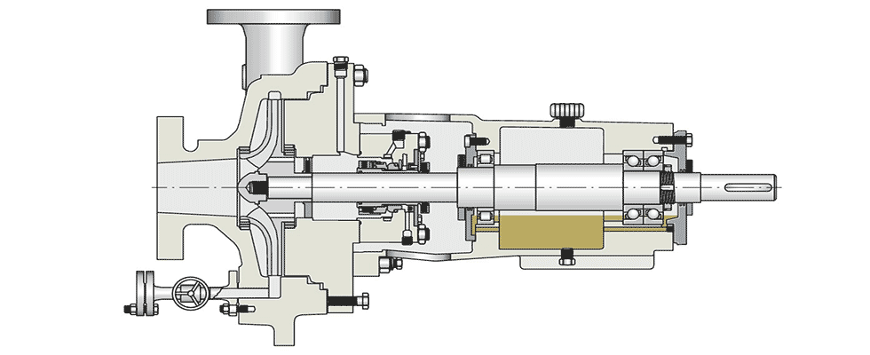
Looking inside a centrifugal fluid pump, two separate bearing positions can be found. The front position closest to the impeller is usually the nonlocating bearing that reacts to the radial loads of the system. A deep groove ball bearing or a cylindrical roller bearing is most commonly used for this purpose. The rear position is typically the axially locating bearing pair, which sets the axial end clearance and reacts to axial as well as radial load. Most centrifugal pumps employ either a double-row angular contact ball bearing (DRACBB), a pair of angular contact ball bearings (ACBBs) or a pair of tapered roller bearings.
Failure Modes
As mentioned above, the three common failure modes in centrifugal pumps are seal wear, skidding damage in the bearings and bearing cage fracture. The first of these failure modes—excessive seal wear—is caused by a deflection of the main shaft, which increases the contact force of the seal against the shaft, prematurely wearing the seal material. Reducing this shaft deflection will extend the life of the seal, which will lead to a longer system life for the pump.
The second common failure mode for centrifugal pumps—skidding damage in the bearings—is caused by insufficient loading on one of the locating bearings. Because the axial force of the pump typically only acts in one direction, only one of the locating bearings takes the majority of the load while the other bearing is used to support any additional radial load and overturning moment. Depending on the operating conditions, this may lead to the unloading of one bearing, whereby the rolling elements tend to spin off their axis rather than roll along the intended direction in the raceway. ACBBs and DRACBBs are especially vulnerable to this mechanism under lightly loaded conditions. Moreover, the centrifugal force exacted on the balls while they are outside the load zone can further exacerbate the change in contact angle that the bearing experiences. This additional spin leads to a phenomenon known as skidding, which can be recognized by slippage tracks on the raceway and rolling elements. Reducing the clearance or even preloading the locating bearings can help avoid this failure mode.
Skidding can also lead to cage fracture, the third common failure mode for centrifugal pumps. Within a lightly loaded bearing, the load zone makes up a smaller portion of the raceway. This can cause the rolling elements in the bearing cage pocket to decelerate or brake as they enter the unloaded zone in the cage pockets and then accelerate when they reenter the load zone and begin rotating normally again. If these accelerations and decelerations are drastic or frequent enough, then the cage can experience fatigue and eventually fracture in the pocket as a result of the higher-than-normal stresses.
Analysis
To investigate these failure modes, a bearing manufacturer selected a user-provided pump and monitored the displacement at the seal, the balls’ roll/spin ratio as well as the cage acceleration across a best efficiency point (BEP). To simulate normal operating conditions, all load cases were run at 1,780 rotations per minute (rpm) with a temperature differential of 10 C (50 F) between the inner and outer ring. Three different pairs of 7313-series ACBBs were simulated in the locating position under the aforementioned conditions with varying clearance ranges. All tested pairs were of universal design (meant for use as a pair in either X or O arrangement) and featured the following clearance classes: UA (small axial clearance), UB (smaller than UA axial clearance) and UO (clearance-free). The clearance in the front 6313-series bearing was set to normal clearance (CN) for all calculations. Based on the loading provided, the motor-side bearing in the locating pair supports the axial load in the system, while the bearing on the impeller side supports any radial load and overturning moment loads.
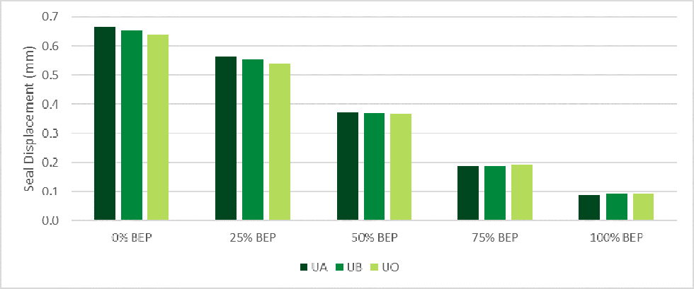
Using these test parameters and three different pairs of ACBBs, the shaft displacement at the seal location was the first condition to be investigated. These deflections can be seen in Image 2. At 0% BEP, the pair of UA-clearance ACBBs resulted in the largest shaft displacement. Meanwhile, the UB-clearance bearings deflected 13 micrometers (µm) less than the UA-clearance versions, while the pair of UO-clearance bearings deflected 27 µm less than the UA pair at the seal location. Similar results were seen at 25% BEP: The UB-clearance pair deflected 11 µm less than the UA pair, while the UO-clearance pair deflected 24 µm less than the UA pair at the seal location.
Although similar results were seen at 50% BEP, it should be noted that the overall deflection of the shaft decreases as BEP increases. The pair of UB-clearance ACBBs deflected 2 µm less than the UA pair, while the UO-clearance bearings deflected 4 µm less than the UA pair at the seal location. At 75% and 100% BEP, the UA pair deflected less than both the UB and UO bearings. At 75% BEP, the UB-clearance bearings deflected 1 µm more than the UA-clearance bearings, while the UO pair deflected 2 µm more than the UA pair at the seal location.
Similarly, the UB-clearance bearings deflected 2 µm more than the UA pair at 100% BEP, while the UO-clearance bearings deflected 3 µm more than the UA pair at the seal location.
There are only marginal differences in deflection at a more optimal BEP range, but there is an advantage at lower BEP with respect to minimizing seal wear due to less shaft deflection.
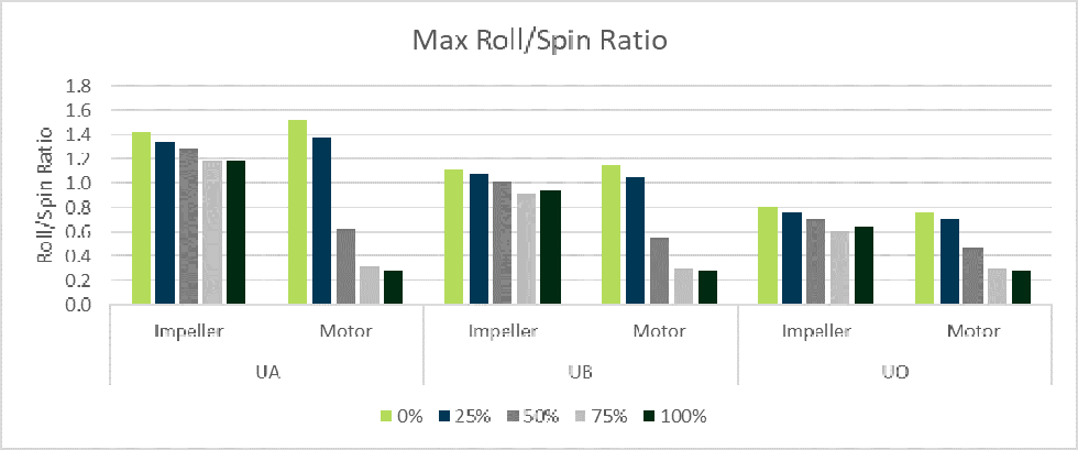
Following the shaft deflection analysis, the roll/spin ratio was the next condition to be investigated. A roll/spin ratio greater than 0.5 has been linked to a higher likelihood of skidding damage in bearings, although this may depend on the lubrication in the system. For this part of the analysis, the bearings in the motor- and impeller-side locations were monitored, and a full output of results can be seen in Image 3.
With respect to the UA-clearance bearing pair, the roll/spin ratio is greater than 1.1 for all BEP cases in the impeller-side bearing; this indicates that skidding would be likely. While the motor-side bearing fairs better once the BEP is increased, skidding is still likely when operating under 50% BEP. Meanwhile, the impeller-side bearing of the UB pair showed a roll/spin ratio greater than 0.9 for all BEP cases—once again, indicating that skidding would be likely. Skidding is still a concern at 0% BEP and 25% BEP in the motor-side bearing; the skidding condition is borderline at 50% BEP. Finally, the impeller-side bearing of the UO-clearance bearing pair showed a roll/spin ratio greater than 0.6 for all BEP cases. This indicates skidding would be likely at 0% BEP and 25% BEP; at higher BEP, the skidding condition is borderline. Skidding is still a concern at 0% BEP and 25% BEP, although the roll/spin ratio is under 0.5 at higher BEP.
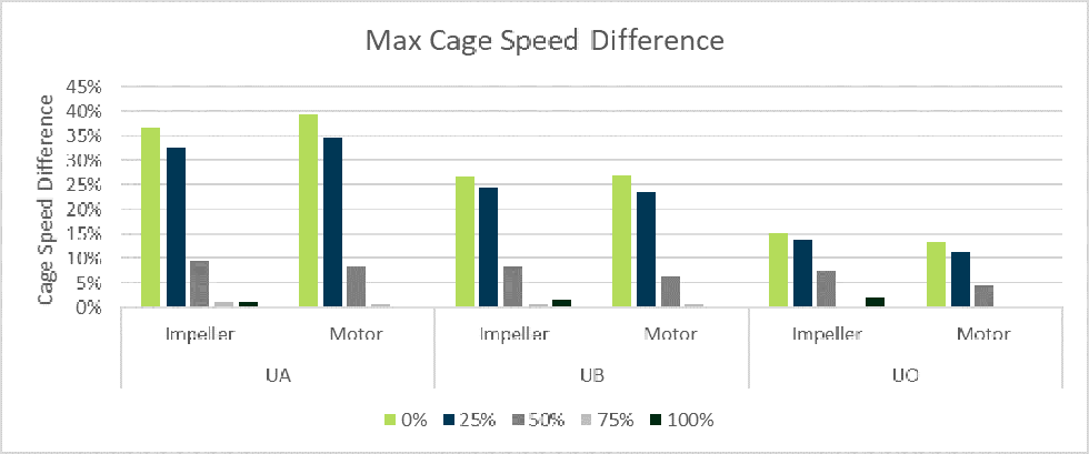
With regard to the third common failure mode for centrifugal pumps—bearing cage failure—the cage speed variation of the bearings showed results similar to the roll/spin condition. This was determined by calculating the orbital speed of each ball in the cage pockets and then using the variance between the maximum and minimum values to generate the cage speed difference seen in Image 4.
Since greater cage speed differences put more stress on the pockets, this condition may lead to fractures. Per Image 4, the UA-clearance bearing pair exhibits the highest cage speed difference; this phenomenon is particularly evident as the BEP decreases. While the UB pair performs better, the lowest cage speed variations are achieved using UO-clearance bearings.
As the preceding investigation into the three common failure modes for centrifugal pumps has shown, selecting the proper bearing axial clearance should improve the life of the bearings and, consequently, the pump itself.
Using a bearing with less clearance limits the deflection at the seal, which, in turn, can help improve seal life of the pump—especially when operating further from optimal BEP ranges. Moreover, the reduced clearance minimizes the amount of potential skidding in the bearings, particularly in the unloaded bearing that is primarily used for moment and radial load.
Choosing the proper clearance can also reduce the stresses in the cage due to accelerations, which can extend the life of the bearing and the overall system. If, however, damage is still seen in the bearings even with a reduced clearance range, then it may be necessary to move to a preloaded bearing to further reduce the likelihood of skidding and cage stress.
