Last of Two Parts
by Lev Nelik

Last of two parts.

In my April 2014 column in Pumps & Systems, I quizzed readers, asking if the pump suction behavior depended on the discharge (system) side of a pump. This quiz also referenced a video that can be viewed at www.pump-magazine.com and go to Q&A, Question 120.

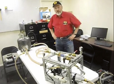
Image 1. Dr. Lev Nelik conducts the experiment shown in the video.

Two tests were conducted during the video. One dropped the suction pressure in front of a pump by throttling the suction valve. The second introduced a vacuum at the supply tank with the suction valve open. In the examples, water was recirculated to the supply tank (see the dashed line in Figure 1) instead of the more common situation in which it is pumped from one tank to another. The readers were asked to explain the differences in the two tests—why the tank vacuum had such a different effect on cavitation when compared to the suction valve throttle.

The Best Reader Answer

The best answer received was from Jim Gagnon, P.E., senior engineer, from CH2M HILL in Cincinnati, Ohio.

Gagnon’s Response

I watched the YouTube video that you posted, and I think I have the solution. In the first experiment, the pumped flow rate decreased when you throttled the suction-side valve because closing the valve added dynamic head to the system. The result is that the operating point moved to the left on the pump curve, and the flow rate decreased.

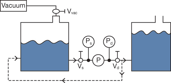
Figure 1. System sketch illustrating the example in the video

In the second experiment, the pump flow rate did not change when you pulled a vacuum on the tank headspace because the pump system is a closed system. The change of pressure in the tank affected the suction-side and the discharge-side equally, so no dynamic head or static head change occurred. The system curve did not move, and as a result, the operating point did not move. However, cavitation became evident (air bubbles in the flow meter) because reducing the pressure in the tank decreased the net positive suction head available (NPSHA) in the system to the point that the pump started to cavitate. I’m looking forward to finding out if I am correct.

Nelik’s Response

You are correct, Jim! Normal flow control of the pump/system is accomplished by closing or opening the discharge side valve—almost never by its suction side. Closure of the valve increases the losses across the discharge valve, and its opening decreases the losses. New system curves are created that intersect the pump curve at new operating points (see Figure 2).

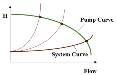
Figure 2. Connection between the discharge performance (H-Q) and cavitation—NPSHR

Once the discharge valve “moves” the pump to a new operating point, its suction characteristics begin to change. It requires less net positive suction head required (NPSHR) at a lower flow and more at a higher flow (see Figure 3).

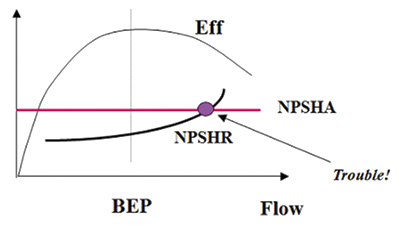
Figure 3. Point at which cavitation develops

Keep in mind that a differential pump head is the difference between the discharge head and the suction head. If the same pressure reduction is applied to the supply tank and delivery tank (as in the second example in the video, the tank was the same), the head (pressure) does not change. The added vacuum cancels out on both sides. The suction and discharge gauge readings change but by the same amount.

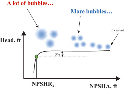
Figure 4. Development of cavitation, starting from the incipient bubble formation and eventually developing to highly unstable bubble activity, their collapse, and damage of the impeller blades

However, if only the suction side is affected (as in the first example with the suction valve closure) but the discharge side remains the same (the pump discharge side sees the same pressure because of the same tank level), a difference exists between the suction and discharge pressures. For example, the pump head (differential pressure) increases, and according to the H-Q curve, the pump hydraulically moves to a lower flow and at a lower NPSHR. This moves the flow farther away from cavitation.

Another tweak can still be made to the example system from the video. At my next Pump School, I will discuss how the NPSHR curve also changes at low flow (compared to the flow in Figure 2) and which pump design features are modified. For more information about the Pump Schools, visit www.pumpingmachinery.com/pump_school/pump_school.htm.

Issue