

The Chinese proverb “A journey of a thousand miles begins with a single step” shows that even the longest and most difficult venture always has a starting point.
In my April Pumps & Systems column, “The Digital Twin: It’s a Journey Rather Than a Destination,” I described how a digital twin of a physical fluid system delivers insight on system operation. I presented examples that show how those system insights are used throughout the life of a facility.
I’m often asked, “When is the best time to start the digital twin journey?” My response: “When you have a reason to go.”
Why Change an Existing System & Why Now?
Yes, there is an ideal time to start: with a green-field project. That way, you can use the digital twin in the design/build phases, then continue into the operate/maintain phases. But, since most facilities with major piping systems are already operating, I’ll focus this article on starting the digital twin journey with an existing system. I’ll cover creating a digital twin for a new project in a future discussion.
The first questions to answer before you invest in digital twin technology are, “Why now, and what’s the benefit?” After all, your facility has been operating all this time without a digital twin, so why change now?
Change presents new risks as well as opportunities for greater rewards. The goal of any change is to maximize the rewards and minimize any inherent risks. Yet that’s the essential value of the digital twin. Instead of trying new ideas on a physical system that’s busy making products, you can model changes or ideas for free and at low risk. If the changes look promising, you can take the next step. If they don’t, you can try a new idea.
A Consistent, Reliable Road Map Guides the Transition
All digital twins are made of the same four parts. First is the mathematical model that simulates the operation of the physical system. The second is the industry-specific information that describes the equipment in the system. The third is the operational information from the system used to set up the model and validate the results. Finally, there are methods of analyzing the calculated values to gain insights to the operation of the physical systems.
In this article, I’ll describe the mathematical model, industry information and operational information you need to create a digital twin. Regardless of your reason for making the digital twin journey, these three steps are fundamental. We’ll then examine how the insight provided is used to reach a successful conclusion to the journey.
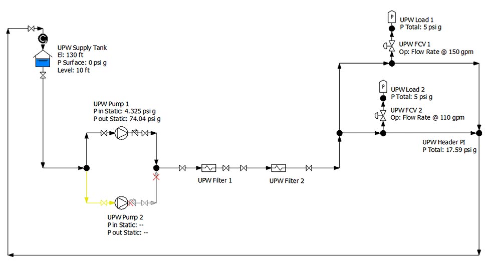 IMAGE 1: An ultra-pure water system with two loads (Image courtesy of the author)
As you can see in the example in Image 1, this is a relatively small system, consisting of closed and open loops with multiple paths. (Note that the process I’ll describe can be used to create a digital twin for a fluid piping system of any size.)
The CMA Model
Since we’re evaluating a fluid piping system, we need to use an appropriate CMA (computer modeling and analysis) application to simulate the system. The objective of the mathematical model is to balance the flow rates and pressures within the system. There are a variety of CMA applications specifically designed for fluid piping systems and many use a drawing interface to build the model.
Image 1 was created with such an application, providing the program interface along with the ability to communicate with other mission-critical applications.
Industry-Specific Information
All the equipment in piping systems falls into one of three categories: a pump element, process element or control element. The pump element provides all the energy needed to move the process fluid through the piping system and consists of a drive and pump. The process elements make the product or provide the services and consist of tanks, heat exchangers, mixers, strainers and other equipment, along with the interconnecting pipelines. The control elements maintain the quality of the product; they consist of valves, instrumentation and controllers, along with additional instrumentation that may be needed to safely operate the system.
For a system that’s already in operation, you can find all the industry-specific information in the design documents. For example, the pump curve and operating instructions supplied by the manufacturer have all the required pump element data. The manufacturer-supplied design and operating data for each item of process and control equipment also can be easily inserted into the digital twin.
You can find information such as tank elevations and sizes on the various design drawings. The pipeline length and nominal sizes are on the piping drawing, along with the number and types of valves and fittings. Once all the as-built data has been inserted into the digital twin, it can be used to simulate the system in any expected operating conditions.
Operational Information
The next step is inserting the operational information into the digital twin. This includes tank levels and pressures, the position of isolation valves and set points for the various control elements and operations of the various pumps. Image 1 reveals that the operational values consist of the UPW Supply Tank level of 10 feet, UPW Pump 1 operating, and UPW FCV1 set to 150 gallons per minute (gpm) and UPW FCV2 set to 100 gpm.
Using this set of as-operated conditions, the digital twin can calculate pressures and flow rates through the system. Notice that the UPW Pump 1 has a calculated suction pressure of 4.325 pounds per square inch gauge (psig) and a calculated discharge pressure of 74.04 psig, while the UPW Header pressure is 17.59 psig. (The remaining calculated results from the digital twin are not displayed on the flow diagram to avoid clutter.)
The next step is to validate the accuracy of the digital twin by comparing the calculated results with the as-observed values on the installed pressure gauges. The installed UPW Pump 1 has an observed suction pressure of 4.3 psig, an observed discharge pressure of 74 psig, and the UPW Header pressure of 17.6 psig. Since the calculated values are within the accuracy of the installed plant instrumentation, the digital twin is accurately representing the operation of the physical system.
With an accurate digital twin of an existing system for a known condition, we can simulate the system under any operating situation. The calculated results of the CMA application provide insight into system operation.
Gaining & Applying System Insight
The validated digital twin can now use the calculated results to gain insight into system operation—and that’s the reason we’ve started this journey. We’ll use the digital twin results to gain a better understanding on how to improve the piping system’s operation.
Piping systems are designed to meet a given set of operating conditions, but once the facility is making product, they’re operated to meet market demands. In our example, plant management would like to know if the existing, as-built system can meet an increased operational flow rate of 20%.
Using the digital twin, plant operations can determine if this is possible. By increasing the flow rates through UPW FCV 1 and 2 by 20%, the digital twin can determine how the system will react to these changes. The calculated results indicate a 2 pounds per square inch (psi) pressure drop across UPW FCV 1, which is less than the minimum differential pressure specified by the control valve manufacturer. Using these results, we can see that the original, as-built piping system is unable to meet the increased capacity requirements.
So, plant management wants to know what can be done to the existing system to enable it to meet the proposed operational changes. After discussions with the equipment suppliers, it was determined the increased capacity could be achieved by either increasing the pumps’ impeller diameter or rotational speed. Each option can be tested with the digital twin.
Since many of the operational decisions were based on an increase in operating cost, the digital twin can calculate the increased annual power cost of each option. The insight reveals that the best option is to increase the impeller diameter of the existing pumps.
A Long-Term Journey With Lasting Value
Once the digital twin journey is completed, it can be used to simulate the operation of the physical piping system under any operating condition. The same digital twin can provide system insight for maintenance, operations, training, energy conservation and system changes. By keeping the digital twin updated by incorporating any and all as-built and as-operating changes, it can be used throughout the life of the plant.
That way, the journey goes on forever—and the value never ends.
To read more Pump System Improvement columns, click here.
