
Oil and gas production wells initially have sufficient pressure for gas and condensate to flow freely from the wellheads through export pipelines to the nearby existing gas plant under reservoir pressure. As the reservoir pressure declines, the peak gas will no longer be attainable. As a result, pumping equipment is needed to assist the recovery as the reservoir production rate and pressure decline. In one case study, the export condensate pump must cover operating conditions related to production rates and pressure deterioration without pump re-bundling or piping modification. The pumps need to handle condensate at various operating conditions. Because of gas well decay, condensate is pumped as a fluid near its vapor pressure and is subject to flash easily with slight pressure or temperature changes. The pressure deterioration in the well leads to an increase in the pump head from 940 to 1,800 meters. Eventually the gas condensate mixture becomes lean (less condensate), and the condensate flow rate falls from 71 cubic meters per hour (m3/hr) to 27.6 m3/hr.
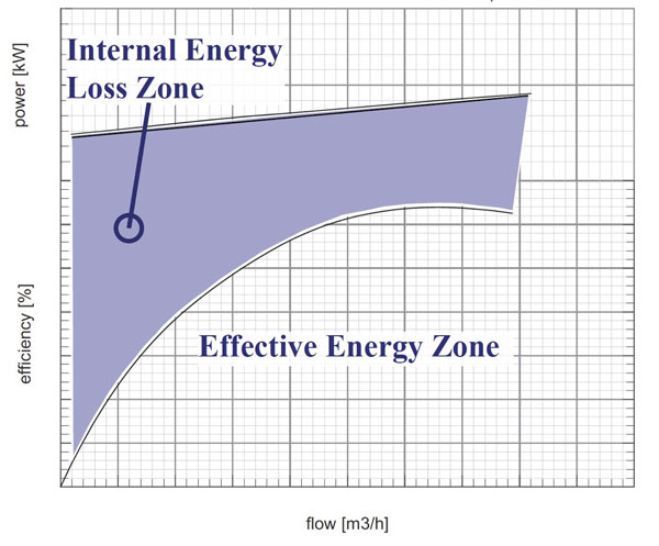 Figure 1. An illustration showing the efficiency loss at low flow rates (Images and graphics courtesy of Enppi)
Pump Selection
The user selected barrel-type condensate pumps that were compliant with American Petroleum Institute (API) 610 BB5. The double casing radially split multistage horizontal pumps have 16 stages in a back-to-back (B2B) configuration. Centrifugal pumps convert only a portion of the power input by the driver into hydraulic energy. The remaining energy is mainly converted into heat. These internal losses in energy depend on the flow rate and eventually get dissipated through the pumped liquid. In most pump curves, the lower the flow rate, the lower the pumping efficiency and consequently the higher internal losses. Having low flow concerns will lead to constraints against low flow rates in high pressure, high power pumps. Temperatures will rise significantly because of the ratio between the power input and the mass flow of the pumped fluid. The temperatures should then be investigated to ensure that no internal flashing occurs because of this temperature rise. Users should also check internal areas such as bushings and wear rings for a rise in temperature.Pump Minimum Continuous Flow
The pump industry uses two terms to define the minimum possible flow rate for safe pumping operation. Minimum continuous stable flow (MCSF) is mainly related to pumped fluid recirculation that may result in cavitation and vibration. Minimum continuous thermal flow (MCTF) is concerned with temperature rise at lower flow rates. The minimum operating flow is the higher of the MCTF and MCSF. Figure 1 shows the relationship between the flow rate, pump efficiency and power absorbed. As the curve approaches lower flow rates, the efficiency drops and the internal losses increase dramatically. This behavior adds heat to the pumped fluid at these low flow rates. This heat addition should be calculated to obtain the required MCTF. Generally, MCSF prevails in most applications with much higher rates than MCTF and becomes the defining variable. In this case, however, MCTF dominated because of the following:- Low specific heat (Cp) value. The condensate Cp is almost half of the Cp of water, so the same energy that would raise water's temperature by one degree Celsius will heat up condensate by two degrees Celsius.
- High-pressure, low-flow operation.
- The pump suction pressure was slightly above vapor pressure, which means that any loss in pressure or increase in temperature caused the pumped fluid to turn to vapor.
- through the pump's 16 stages where pressure develops.
- because of the throttling of the condensate in the clearance of the thrust balancing device.
Thrust Balancing Systems
Thrust balancing is a necessary part in every centrifugal pump arrangement. Thrust forces are magnified in high pressure, multi-stage pumps to a level that should be eliminated or at least reduced. Net thrust values could be enhanced by:- the B2B arrangement provided to the impellers of the pumps. a thrust-balancing device with a leak-off line to eliminate the residual thrust forces in the pump. This will increase the rotor dynamic stability and improve axial thrust compensation.
.jpg) Image 1. Pump arrangement installed at site showing the return line location to the first stage
Image 1. Pump arrangement installed at site showing the return line location to the first stage- improper thrust balancing and less rotor dynamic stability.
- mechanical seal malfunction that may lead to seal failure.
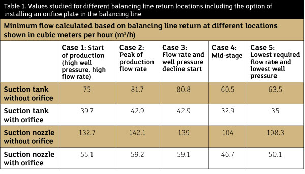 Table 1. Values studied for different balancing line return locations including the option of installing an orifice plate in the balancing line
Balance Routing Options
One condensate pump OEM offers BB5 pumps with a design option to route the discharge of the first stage. Image 1 shows the pump arrangement installation. This means the balance leakage at the bushing will move from eighth-stage pressure to first-stage pressure (which varies in the presented cases from 3.6 to 7.4 bars) instead of suction. At the same thermal energy level introduced to the liquid condensate, the possibility of condensate flashing to vapor at high pressure (in the first stage) decreases. So the MCTF (shown in Table 2) is lower with a wider pump operation range. These examples show that the more pressure exists at the balancing line exit, the less flow is required to overcome the heating (the less MCTF). Any flow recycle is an energy waste and will decrease the process efficiency.Balancing with the First Stage
The mechanical seal in the balancing line side is exposed to the suction pressure plus the pressure of the first stage. This raises the design pressure of the mechanical seal slightly. Because this mechanical seal is a double seal with barrier fluid and accumulator (Fluid Sealing plan 53B), operators must consider that the seals installed on the pump, drive and non-drive sides have about 10 percent difference in seal pressure. So the setting of the accumulator pressure and the recharging time are different in the two seals. The leakage rate for a mechanical seal exposed to suction plus first-stage pressure is higher than the leakage rate for a mechanical seal exposed to suction pressure only, which is around 5 percent in this case. Table 2. Values studied after applying balancing line return location to the pump first-stage impeller