
In sewage grinder pumps, domestic wastewater from one or a few households flows by gravitation to a pumping station equipped with one or two grinder pumps, having a discharge pipe of nominal diameter (DN) 40 or DN 50. This pumping station discharge pipe DN 40/50 is connected to the main sewer via small pipes. During operation, all pipes from several locations are pressurized up to several bars, resulting in the pressure class for the pipes to be at least nominal pressure (PN) 6. In most cases, the pressurized system is connected to a gravity sewer. The one-way-in, one-way-out fishbone-shaped network must not contain any loops. Free passage is necessary for proper results. The volume of the station accommodates all the domestic wastewater generated during a 24-hour period. Service staff members have adequate response time in case of a service interruption.
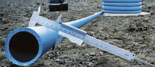 The pipes used in pressurized systems are most often delivered on reels and are unrolled as they are lain into the pre-dug ditches. The depth depends on local regulations and frost conditions. (Images and graphics courtesy of Grundfos)
Grinder Pump Design
Grinder pumps are specifically designed to pump untreated sewage from a limited number of households. The grinder system at the pump inlet grinds the household waste carried by the water. The wastewater should not contain water from roofs or other hard surfaces with sand or small stones. The particles could cause abrasion, damaging the grinder system and clogging the pump inlet. The grinder pump system should have parts that are easy to replace, reducing downtime and facilitating maintenance. One grinder system’s specialized impeller-clearance adjustment system ensures high discharge pressure to transport the wastewater longer distances.System Design & Calculation
To prevent sedimentation and air accumulation in the pressure pipes, the velocity in the pipe must be at least 0.7 meters per second (m/s). In landscapes that are extremely hilly (with slopes that are greater than 10 percent), air release valves should be installed at the high points.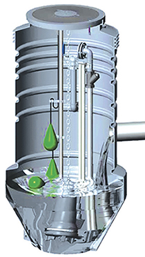 The sloping sides and narrow bottom of the sump design help prevent sedimentation.
Recommendations
During the design phase, pipe diameters should be determined while considering the pump capacity for the working pumps installed farthest from the system’s outlet point (treatment plant or gravity pipe).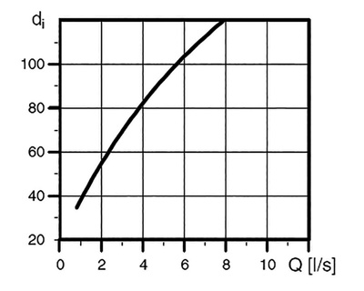 The figure shows the relationship between inner diameter of the discharge pipe (di) and the flow (Q), according to EN 12050-1. The curve shows a velocity of 0.7 m/s.