
Construction features are key to vertical motor application and maintenance.
The definite-purpose application of vertical motors dictates a number of construction features that set them apart from horizontal motors. Some differences are obvious—such as a vertical motor typically drives a pump and has a P-base mount without feet and a horizontal motor may have a footed or footless mount with a C or D flange or no flange). Less apparent is the unique capacity of vertical motors to carry external thrust. For optimum service and performance, understanding how construction features affect application and maintenance requirements is important.
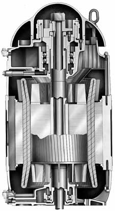
Figure 1. Typical vertical motor
Vertical Motor Classifications
Vertical motors can be broadly classified based on shaft type—solid or hollow. Solid-shaft models couple to the pump shaft at the lower end of the motor. The shaft extension on these motors normally has an annular (ring-shaped) keyway to carry the thrust of the pump and a radial keyway to transmit torque. This type coupling is more common on shallow pumps and tanks than on deep-well applications.
On hollow-shaft motors, the pump headshaft passes through the motor shaft and couples at the top of the motor. An adjusting nut at the top of the headshaft greatly simplifies the adjustment of the pump impeller depth. Although commonly used on deep-well pumps, hollow-shaft motors may be applied whenever easy adjustability is an advantage.
Vertical motors are also classified by their thrust load: normal, high or in-line. Normal thrust loads can be determined from tables based on motor speed and horsepower rating. High thrust is a multiple of normal thrust—for example, 175 percent, 250 percent or 300 percent. In-line pump motors are a little different because the pump is “in line” with the piping, no external thrust is applied to the shaft.
Thrust Bearings
The thrust bearing, which is usually at the top of the vertical motor (Figure 1), may consist of one or more angular contact bearings; a spherical roller bearing;
or a hydrodynamic, plate-type bearing. The thrust applied by the pump—manifesting in upward, downward or balanced axial loading—determines the type and number of bearings used. The applied load and speed of the thrust bearing may require oil lubrication. To achieve the best service life and performance, it is important to correctly match the thrust bearing configuration and the pump thrust.
Angular Contact Ball Bearings
Angular contact ball bearings are the most common thrust bearings in vertical motors. A single bearing is used for normal thrust loads. Two bearings can be used in tandem for 175 percent of normal thrust (see Figure 2), and three bearings can be stacked for 250 percent of normal thrust. Stacks of up to five bearings have been reported. (Note that using two bearings in tandem does not double the thrust capacity.)
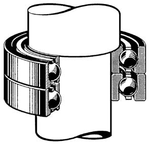
Figure 2. Angular contact ball bearings
Spherical Roller Bearings
Spherical roller bearings are used when even higher thrust loads are applied (Figure 3). Such high-thrust loads are common on very deep wells, where the column of water, the pump shaft, the impeller and the force applied to move the water can total several thousand pounds. Spherical roller bearings can handle 300 percent or even 500 percent of normal thrust load.
Hydrodynamic Bearings
Hydrodynamic—tilting pad, plate or Kingsbury—bearings (Figure 4)can handle extremely high thrust loads. Like sleeve bearings in horizontal motors, they can last a long time. The load is carried on an oil film that separates the moving parts, so theoretically, no wear on the plates occurs.
Guide Bearing
The bearing opposite the thrust bearing (usually the lower or “bottom” bearing) is called the guide bearing (Figure 5). Its function is to locate the lower end of the motor shaft and withstand momentary upthrust (i.e., 30 percent of standard high thrust in the direction opposite the thrust bearing for no more than ten seconds). The guide bearing is typically a Conrad deep-groove ball bearing and is usually grease lubricated. In normal operation, it is subject to little or no load.
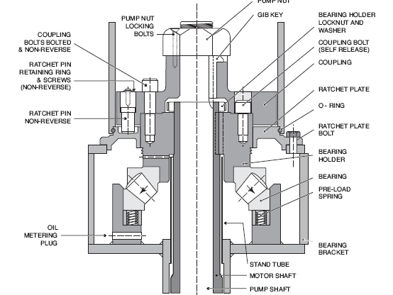
Figure 3. Spherical roller bearing
Special Thrust Case
Occasionally, a pump design will exceed the momentary upthrust limits (more common with 3,600-rpm designs). If the guide bearing cannot accommodate this thrust for the duration necessary, the upper bearings are arranged back-to-back (Figure 6) or face-to-face. (Note that arrows indicating thrusts in the bearings are in opposite directions.)
Such configurations require additional parts. For example, a hold-down ring must be mounted on the outer race of the upper bearing and fastened to the upper bracket to prevent the upthrust from lifting the bearings from the bearing bore. A nut must also be threaded onto the bearing carrier below the lower bearing inner race to keep the upthrust from pushing the bearings off the mount. The motor vendor should be informed if the application experiences upthrust, so that these steps can be applied.
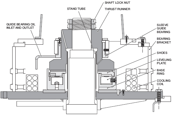
Figure 4. Tilting pad bearing
Accessories
Other options are available for vertical motors.
Steady Bushing
To prevent pump seal damage from “shaft whip” and excessive vibration, a brass steady bushing can be installed at the lower end of hollow shafts to stabilize and center the headshaft. If the hollow shaft extends beyond the motor's lower end bracket, it will be installed as shown in Figure 7. If there is no shaft extension (such as with an oil-lubricated lower bearing), the steady bushing will be machined and pressed into the hollow shaft.
Non-Reverse Ratchets
Non-reverse ratchets (See Figure 8) prevent pump backspin when the power is off and the column of water falls through the pump impeller. Depending on the well depth, backspin can reach dangerous speeds if unchecked. As the water level falls, it leaves the water-lubricated pump bearings without lubricant.
Two common types of non-reverse ratchets are ball ratchets and pin ratchets, both of which work on the same principle.
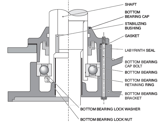
Figure 5. Guide bearing
Centrifugal force supports the balls or pins until the rotating speed drops enough that the weight of these elements overcomes it. As the rotor comes to rest and begins turning backwards, a ball or pin engages a stationary tooth to stop rotation. An odd number of teeth versus balls/pins ensures that the ratchet will travel only a few degrees before stopping its reverse rotation. The ratchet is robust to withstand full motor torque in reverse. So if the motor can lift the column of water, the ratchet can stop backspin from that same column.
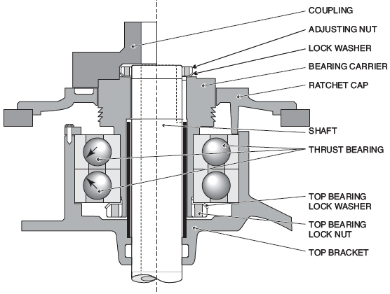
Figure 6. Back-to-back bearings
Lubrication
Table 1 lists some turbine oil lubricants that are suitable for use in vertical motors, as well as the ISO grades and corresponding viscosities. It is important to use the correct viscosity relative to the ambient temperature conditions of the motor application. If the oil is too thin (low viscosity) to maintain the separation of the rolling elements and races, the bearing will be damaged. If it is too thick (high viscosity), fluid shear in the oil will create excessive temperature that will quickly degrade the oil.
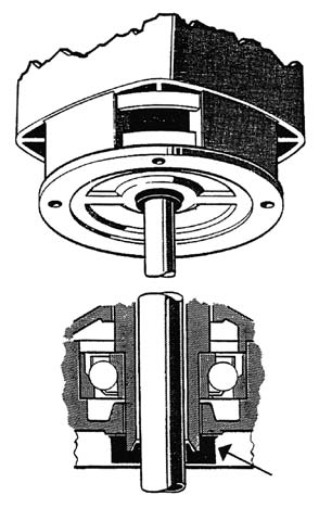
Figure 7. Steady bushing
Large, enclosed motors and motors with roller bearings usually require external oil cooling. The extra material and effort necessary to provide this can often be avoided by using synthetic turbine oil. The synthetic will operate successfully at temperatures 30 degrees C higher than mineral-based oils.
Replace the oil according to the motor manufacturer's guidelines. As an alternative, test it regularly for oxidation, contamination (e.g., wear metals or moisture) and viscosity, and then replace it when tests show degradation.
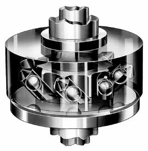
Figure 8. Non-reverse ratchet
Vertical Motor Lubrication Cautions
These hard-learned lessons describe common pitfalls of vertical motor lubrication:
- Changing the oil viscosity may cause leaking or overheating.
- Do not mix oils. They may not be compatible.
- If water cooling coils are used, check for water leaks.
- Some thrust bearings must be preloaded beyond the rotor weight. Check for warning plates on the motor.
- Rotating the rotor shaft by hand may require a strap wrench due to the high downward loading on the thrust bearing -- especially with plate-type or spring-loaded bearings.
- When servicing the motor, drain and replace lubricating oil.
- Oil sump temperatures:
- Normal 80 degrees C mineral/110 degrees C synthetic
- Alarm 90 degrees C mineral/120 degrees C synthetic
- Shut down 100 degrees C mineral/130 degrees C synthetic
- Hollow-shaft motors may use a steady bushing.
- Motor lifting devices lift only the motor.
Conclusion
Vertical motors are unique in their ability to carry external thrust. The thrust bearings that make this possible require care for optimum service and performance. Oil-bath lubrication is a special consideration for vertical motors that must be understood and maintained correctly.
.jpg)
Table 1. Recommended bearing oils for typical vertical motors
Pumps & Systems, September 2011
