
This is a follow-up to my column on predicting centrifugal pump performance (Pump & Systems, May 2011), and offers equations that will enable the engineer to perform a partial analysis of the impeller eye.
Nomenclature:
b1 = width of the vane at the inlet edge (inches)
C1 = absolute velocity of the fluid at the vane inlet (ft./sec.)
Cm1 = meridional component of the relative velocity, W1 (ft./sec.)
D1m = diameter at the midpoint of the vane inlet (inches)
N = rotative speed of the impeller (rev./min.)
P1 = meridional velocity of the fluid when there is no pre-rotation (ft./sec.)
Q1NP = the capacity (flow rate) at the impeller eye when there is no pre-rotation (U.S. gal./min.)
Q1OPT = the capacity (flow rate) at the impeller eye when the eye is oversized enough to produce a right angle between C1 and W1 (U.S. gal./min.)
t1' = average vane thickness at the impeller eye, measured normal to the vane surface (inches)
u1 = tangential velocity of the impeller vane at the midpoint of the leading edge (ft./sec.)
W1 = velocity of the fluid relative to the impeller at the midpoint of the vane's leading edge (ft./sec.)
Z1 = number of vanes at the impeller eye
β1 = angle of the impeller vane at the leading edge of the vane (degrees)
β1m = angle of the impeller vane at the midpoint of the leading edge of the vane (degrees)
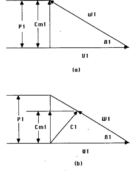
Figures 1a (top) and 1b (bottom)
The Equations
Figures 1a and 1b show two different inlet velocity triangles. For maximum pump efficiency, the eye is designed for no pre-rotation at the best-efficiency-point (BEP), as shown in Figure 1a. The capacity of such an eye can be calculated with Equation 1.
Q1NP = Nb1D1m (πD1m sin β1m - t1'Z) / 73.5 cos β1m (1)
To reduce the NPSH requirement at the BEP, the eye is made larger, with a resultant pre-rotation, as shown in Figure 1b. (Pump efficiency will be reduced.) When there is enough pre-rotation for C1 to be at a right angle (90 degrees) to W1, the capacity of the eye may be calculated with Equation 2.
Q1OPT = Nb1D1m cos β1m (πD1m sin β1m - t1'Z) / 73.5 (2)
I refer to this capacity as "optimum" because it seems to be a reasonable balance between efficiency loss, NPSHR reduction and pre-rotation. Stepanoff [2] stated that a P1/Cm1 ratio of 1.8 was "widely used by the industry," and ratio values of 2.0 "were resorted to" reduce NPSH requirements (at the BEP). Such oversized eyes have resulted in significant suction recirculation problems.
Example
A 2 x 3 x 8 horizontal, end-suction, process pump where:
b1 = 1.06 inches
D1m = 2.75 inches
N = 3530 rev./min.
t1' = 0.19 inches
Z1 = 5 vanes
β1m = 17 degrees
Q1NP = (3530) (1.06) (2.75) [π2.75sin17° – (0.19) (5)] / 73.5 cos17° = 233 U.S. gal./min.
Q1OPT = Q1NP cos2 β1m = 233 cos217° = 213 U.S. gal./min.
The calculated Q1OPT is right at the Qbep as shown by the published curve, indicating an eye designed for the "optimum" capacity.
Equations 1 and 2 are for single-suction (one-eye) impellers. If the impeller is double-suction (two eyes), the capacities are twice the above values.
Experienced designers will recognize that my equations use D1 and β1 at the midpoint of the vane inlet, whereas it's more normal for designers to reference them at the point at which the vane intersects the shroud (D1O & β1O). The midpoint seems to yield more accurate results.
Plain Vane Versus Francis Vane Impellers
Many process pumps use a "plain" vane design. A plain vane has a single degree of curvature. The inlet vane angle (β1) is constant across the width of the vane. This results in lower costs of the pattern and impeller casting but also in slightly lower efficiency and higher NPSHR. A Francis vane has two degrees of curvature, twisting as it turns into the eye. The manufacturer that spends more to get a well-designed Francis vane impeller is rewarded with a higher efficiency and lower NPSHR.
References
- Stepanoff, A. J., Centrifugal and Axial Flow Pumps, John Wiley & Sons, New York, 1948.
- Stepanoff, A. J., Pumps and Blowers—Two-Phase Flow, John Wiley & Sons, New York, 1965.
- Jekat, Walter K., "Centrifugal Pump Theory," Section 2.1 of the first edition of the Pump Handbook, edited by Karassik, Krutzsch, and Fraser, McGraw-Hill Book Co., New York, 1976.
Pumps & Systems, July 2011
