
Major infrastructure upgrades handle the pressure from a Mexican drainage system.
 Two big wastewater pump stations with high performance submersible motor pumps relieve flooding during the rainy season to protect thousands from damages. They form part of the millennium infrastructure project in the Valley of Mexico. State-of-the-art hydraulic engineering tools were used to ensure reliable and efficient operation.
Increased Demand
The Mexico City Valley experiences increasing population and rapid urbanization, and the demand for water and sanitation climbs constantly. This demand has been met by a growing system of wells drilled into the soft aquifer underlying the region. This intense exploitation has significantly lowered the ground—up to 50 centimeters per year in some areas.
In addition, spreading urbanization has caused the loss of forests in the surrounding mountains, which has led to decreasing rates of storm water percolation. It also increases the amount of wastewater to handle and treat. Soil subsidence and storm water surges threatened to collapse the existing infrastructure.
Necessary Upgrades
In February 2010, a sewer canal ruptured during heavy rainfall. The Chalco neighborhood was flooded. The National Water Commission (CONAGUA) is combating the devastating consequences with several major infrastructure upgrade measures. The pump station, La Caldera, forms an essential part of one project—the tunnel “Río de la Compañia”—that will help avoid flooding in the municipalities of Chalco (Valle de Chalco, Solidaridad and Ixtapaluca) in the eastern part of Mexico City Valley.
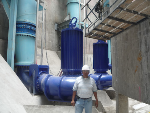
Inaugurated on March 8, 2011, by President Felipe Calderón Hinojosa, the pumping station is intended to lift the water arriving through the tunnel approximately 30 meters in an open drainage channel. From there, it flows by the ancient Texcoco lake area. The pumping plant consists of one sump where mechanical screens are installed and two pump sumps, each accommodating 12 pumps inside a cylinder of 20 meters in diameter and around 35 meters deep.
The Caracol and La Caldera Pump Stations
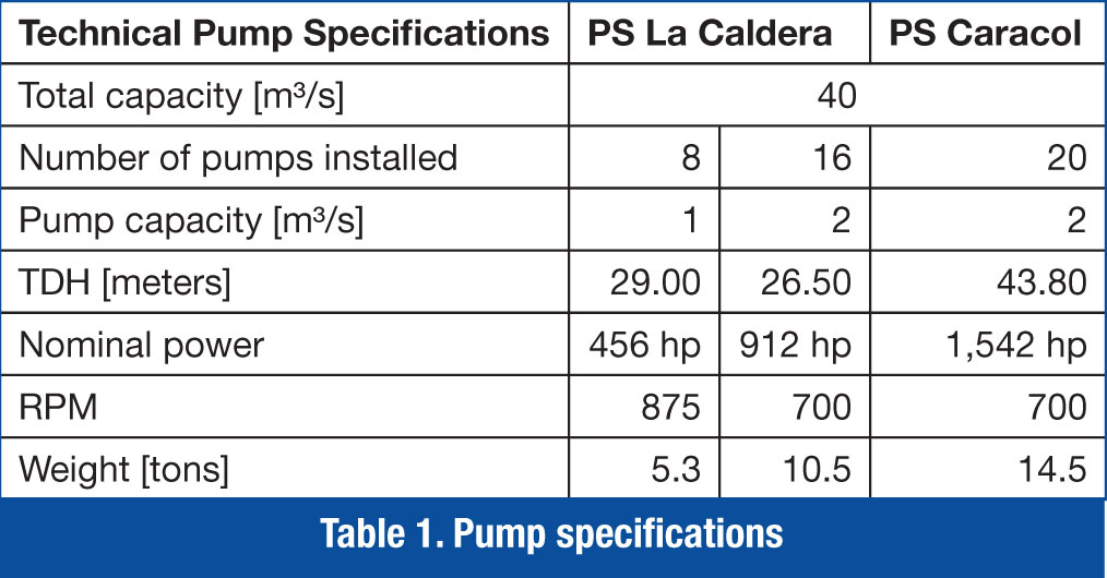
A similar design concept was applied on a second pumping station. The Caracol pump station is being constructed in the federal zone of the Texcoco Lake and is projected to discharge 40 cubic meters per second (m3/s) of combined sewage from the Tunnel Emisor Oriente to the Gran Canal open sewer channel. Twenty large submersible pumps will lift the fluid more than 40 meters. The pumps were supplied by a submersible motor pump company and are specially designed for heavy-duty wastewater applications.
In the La Caldera plant, eight of the 24 units (four per sump) supplied, handle a 1 m³/s of municipal sewage each, totaling the 8 m³/s that system designers consider to be the maximum dry-weather flow. Sixteen pumps with a capacity of 2 m³/s each were projected to join in operation during storm water flow, raising the total pump capacity to 40 m³/s.
In the Caracol pump station, each of the 20 units will pump 2 m³/s. The dry weather flow will be handled by four pumps per sump. Twelve units will take care of peak flows during the rainy season.
The pump design engineers faced several challenges. The huge medium-voltage motors had to develop up to 1,600 horsepower and still fit in the general series design concept. Moreover, the standard guide system for lowering and lifting the pumps in and out of the sump had to be adapted to site conditions.
The engineers de-signed a device that would allow automatic connection or disconnection of the lifting crane’s chain without the need to see any part of the pump in the up to 50-meter-deep sumps or maintain the chain connected to it.
The greatest challenge was to find a sump design that would allow the end user to operate both plants in an efficient and reliable way. The pump company was contracted to create a basic design that would fit in the given dimensions and optimize the same flow through computational fluid dynamic simulations, as well as a physical model test. The goal was to reduce the energy of the incoming flow and to provide the pumps with favorable suction-side conditions.
The flow was intended to approach each pump with limited and equally-distributed velocities, as well as without pre-swirls. Surface and submerged vortices should not occur in any part of the sump. Air entrainment had to be avoided.
Some wastewater-specific issues had to be observed. For example, flow velocities were not expected to fall below a certain value to avoid sedimentation of the solid parts within the pumped medium. No dead zones were desired. All this had to be combined with the demand for a separation between dry weather and rainy season pumps.
.jpg)
Figure 3. Snapshots of the CFD simulation (top, La Caldera PS; bottom, Caracol PS)
Computational Fluid Dynamics
The use of computational fluid dynamics—CFD—(numerical flow simulation) is becoming more important. The software specially developed for this application was effective and allowed for relatively precise predictions of the flow conditions.
Figure 3 shows how the optimized design looks when elaborated through multiple simulation turns.
In both cases, the incoming flow will lose much of its energy in a pre-chamber, from which the flow is directed to the dry-weather pumps.
At a certain water level, the incoming flow brims over to the sump’s rain-weather section. Therefore, the heavier, polluted wastewater stream will remain in this part of the sump and not be distributed to the whole sump.
A protective wall guarantees that the approaching velocities remain within acceptable limits (with respect to absolute values, as well as distribution profiles close to the pump’s suction inlets) despite the fact that 20 m³/s mean a huge amount of kinetic energy.
The design was developed to maintain minimum velocities close to the sump bottom even during low-flow periods, which is vital to limiting sediment built-up in the sump. Dead zones could be completely eliminated.
Additional design features were necessary to prevent the pumps influencing themselves and prevent the formation of entrained air on the surface vortices.
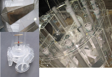
Figure 4. Scale model of the CFD-simulated equipment
Scale Model
The design that was most suitable after the CFD simulation was converted to a geometrically corresponding scale model made of transparent materials (see Figure 4) and installed in the pump company’s laboratory. Through observations made with the model, the pump engineers could verify if the concept they had developed in the computer model worked effectively.
A physical model test is still the most reliable way to identify precisely where problems might arise and how to tackle them. To judge vortex development, for example, the fluid surface, as well as walls and floor areas, were observed. Vortex intensity in a given area was seen using dyes injected into certain sump areas.
Flow velocities were measured at reference points across the model pump’s entire suction cross section via pitot tube. Mean flow velocities should not deviate more than 10 percent from pre-defined values. The pre-swirl angle with which the suction flow approaches the pump was measured by a vortometer. Variations of plus/minus five degrees were acceptable.
The application of dimensionless coefficients enabled the engineers to transfer the results to the full-size structure. However, occurrences that had minor effect in the model may be considerably more significant in the full-scale structure.
Pump Station Results
The pumps supplied to the La Caldera station showed excellent performance during field tests and have been working satisfactorily since March 2011. Service personnel from the pump company will commission the pumps in the Caracol pump station in spring 2012.
Also read web-exclusive interview from Dr. Rafael B. Carmona Paredes, director of the general coordination of engineering and technology and of the coordination in general of special projects for clean water and wastewater at Conagua.
Pumps & Systems, March 2012
