The importance of knowing your flow rate
Engineered Software

Knowing the flow rate within a fluid piping system is one of the most useful measurements in understanding system operations.

The equipment used to measure flow rates is typically maintained and calibrated by the plant instrumentation and control groups. Facility flow meters typically monitor custody transfer or are used as the primary elements of flow control circuit.

Meters used for custody transfer are designed to provide accurate and repeatable values for flow rates when products are sold or purchased. These types of flow meters often measure a positive volume when dealing with small quantiles, or the volume can be totalized over time when measuring large quantiles. The value of flow rate used for custody transfer also helps operate and maintain other plant equipment.

When the design objective of a piping system is to establish a set flow rate of a process fluid, a flow control loop is used (see Image 1). The control elements of the system work together to achieve the proper flow rate.

sample system
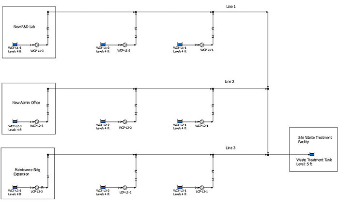
Image 1. Flow rates and system operations (Image courtesy of the author)

The flow meter measures a value that is a function of the flow rate through the meter. The meter then transmits a measured value to the controller. At the controller, the desired value for the flow rate is entered.

The controller then compares the measured value from the meter to the set value and sends an output signal to the actuator. The actuator then adjusts the final element (a control valve or a variable frequency drive [VFD]) to eliminate the excess energy needed to balance the flow rate to the set value. The controller provides the operator with actual measured flow rate.

The initial cost of the equipment and the effort needed to calibrate and maintain these types of flow meters can be cost prohibitive for wide use within a plant. In this column, we will look at ways to measure the flow rate within a piping system without the expense of the custody transfer meters or the complexity of a flow control loop.

Types of Flow Meters

Flow meters fall in two general categories: those that determine the flow based on the pressure drop across the meter, and those that measure a value that has a linear relationship to the flow rate through the meter.

Differential pressure flow meters consist of a flow restriction within the flow stream that causes a differential pressure across the meter. Based on the Bernoulli principle, the flow rate through the meter is a function of the square root of the differential pressure across the flow restriction. The meter takes the square root of the differential pressure and displays the results on a calibrated scale showing the flow rate.

A linear flow meter consists of a measured signal that is directly related to the flow rate through the meter.

Differential Pressure Meters

The most common flow meter is a differential pressure meter consisting of an orifice with a concentric round hole machined to a specific value.

The orifice provides the restriction to flow, while pressure taps on the upstream and downstream side of the restriction provide the necessary differential pressure.

When the process fluid passes from the upstream pipeline into the meter, the restriction in the orifice causes an increase in the velocity of the fluid as it passes through the restriction. Within the restriction, some of the pressure head is converted to velocity head.

After passing through the restriction, the flow slows down as a result of the conversion of velocity head back to pressure head. Knowing the physical laws behind this relationship, we can determine the flow rate based on the pressure difference. Working through the equations shows that the square root of the differential pressure across the orifice plate is a function of the flow rate through the orifice.

The reason for the wide acceptance of orifice plates is their simple operation. They can be incorporated using readily available instruments to read differential pressures and are easily manufactured to meet design flow requirements. In North America, orifices can be sized using standards developed by the American Society of Mechanical Engineers standard (ASME-MFC-3M), or the American Petroleum Institute (API) standard 2530. The standard provides requirements for the location of the differential pressure taps and the method for sizing the diameter of the hold in the orifice plate.

Since the operation and accuracy of the orifice plate is well understood, and the orifice plate and pressure taps can be located at flange faces within a piping system, this style of flow meter can be locally fabricated and inserted in the pipeline when needed.

An annubar is another type of meter that can be inserted into a pipeline for accurate measurement of the flow rate. The meter works by measuring the difference between the total fluid pressure and the static pressure over a large cross-sectional area of the pipeline. The design of the annubar allows it to be easily inserted into the flow stream when needed. This type of meter is designed and tested by the product manufacturers prior to installation.

Linear Meters

Next, we will look at meters where the measured value in the meter is a direct function of the flow rate through the meter.

A vortex meter uses a specially designed bar inserted into the flow stream to create fluid vortexes within the flow stream. The meter counts the number of vortexes created over time, which is a linear function of the flow rate through the meter.

Vortex meters are available from a variety of instrument manufacturers as a total unit. The bar inserted into the flow stream causes a loss in pressure, but it is much less than the pressure drop caused by an orifice plate.

Ultrasonic flow meters measure the frequency change of a sound wave traveling through the process fluid. Ultrasonic flow meters can measure based on the time of flight of the sound wave through the process fluid or the change in frequency caused by the Doppler effect.

In a time of flight flow meter, a transducer projects a sound wave into the pipe. The sound wave travels through the process fluid and is reflected off the opposite pipe wall. Then it travels to a second transducer downstream from the first.

A second sound wave leaves the downstream transducer and makes the trip in the opposite direction. Knowing the distance and the time taken to make the round trip provides the meter with the speed of the fluid in the pipe, providing a linear relationship with the flow rate through the pipe.

In a Doppler-type meter, a transducer sends a sound wave at a given frequency into the flow stream.

When the sound wave is reflected off a small particle or bubble within the flow stream, frequency of the reflected sound wave changes. Using the Doppler principle, the meter measures the change in frequency of the sound wave to determine the velocity of the process fluid. The fluid velocity provides a linear relationship between the fluid velocity and the flow rate.

Measuring the Flow in a Pipeline

Installing a flow meter within a piping system is an expensive process. Therefore, most flow meters are used for custody transfer applications or when the flow rate with a process is required to meet the system design requirements.

As we have discussed in previous columns, knowing the flow rate through a pump, pipeline, heater or control valve can be useful in determining if that equipment is operating properly or needs maintenance. All the examples presented in this column can be installed for use within the piping system when needed. For example, an orifice can be installed between existing flange faces connecting pipe segments. Annubars can be quickly inserted into a pipeline when the plant is shut down and will provide a flow rate when needed.

A vortex meter must be installed in a pipeline, but the calibration and maintenance of this type of meter is less than a typical differential pressure meter.

Finally, portable ultrasonic flow meters can be installed to the outside of a pipe without affecting system operation. The meter can be affixed to the pipe and the flow rate measurement can be taken when needed, and then it can be moved to a different location.

Each of these types of flow meters will provide excellent results when used properly, helping end users gain a clear picture of the operation of the total piping system.

To read more Pump System Improvement columns, click here.

Issue