
Problematic tasks can require improved performance in extreme operating conditions.
01/24/2019
There are applications where the use of a mechanical seal would either not be considered or present major technical challenges. Here are some unusual examples of how mechanical seals can be applied to solve problematic sealing tasks.
Latex
Liquid synthetic latex is an emulsion of polymer particles suspended in an aqueous solution. It is used in making coatings, glues and gloves and more.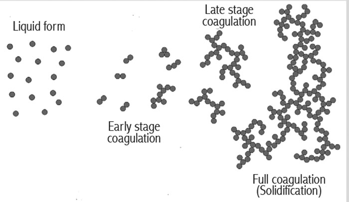 Image 1. Stages of latex solidification or coagulation when exposed to heat or friction (Images courtesy of FSA)
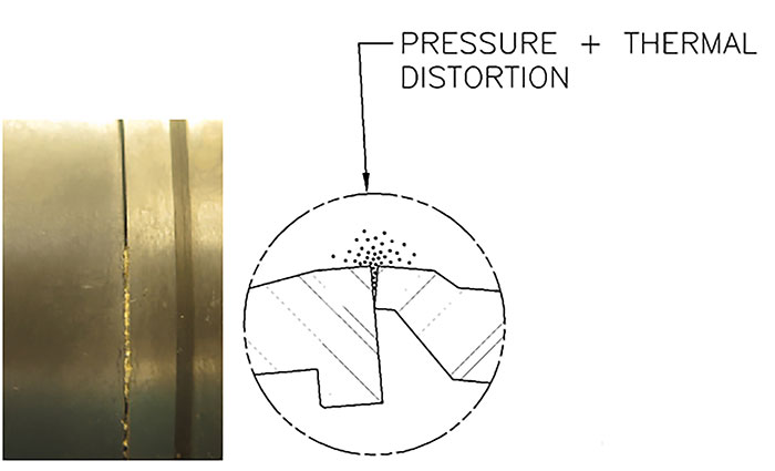 Image 2. Convex faces and latex penetrating the OD, causing face separation
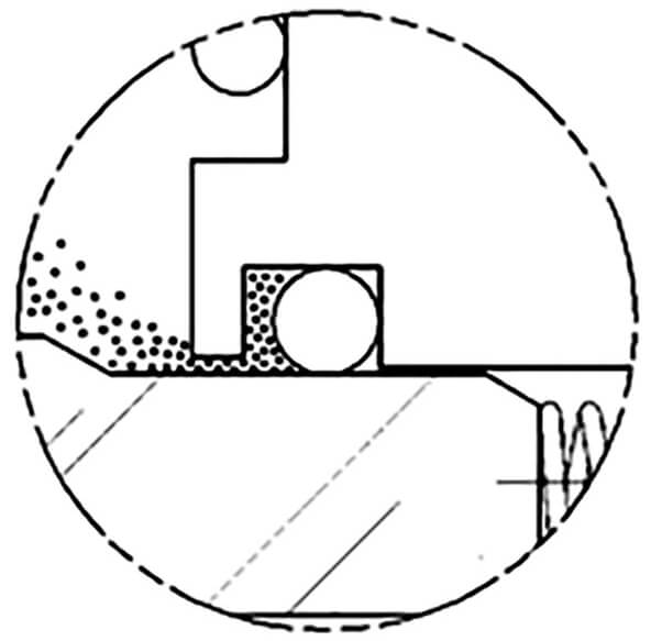 Image 3. Latex accumulating around the inboard dynamic O-ring
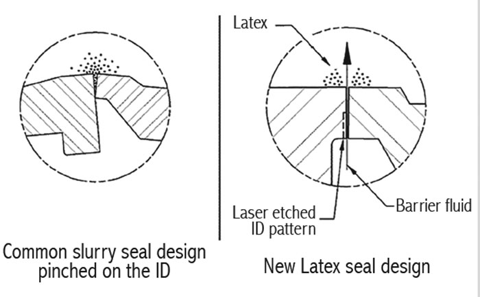 Image 4. Comparison between common slurry seal face design and new slurry seal face design
- increased operational cost due to the continuous supply of external flush
- dilution of the final product, as water is usually used as a compatible external flush
- external flush remains active at all times, even when the seal is static
- seal performance dependent on the reliability of the Plan 32
- seal usually fails once the bushing or lip seal separating the Plan 32 flush from the inboard seal wears out
Turbochargers & Expanders
Expander machine units have largely been used as waste recovery systems for conversion to power and/or electricity, using different seal solutions to varying degrees of success. Simple seal types used in early development of these machines proved unreliable. One example of these earlier seals is the polytetrafluoroethylene (PTFE) seal ring (scarf-cut design) shown in Image 5. These rings are used to seal and minimize process product loss, and also to prevent cross-contamination of process media and gearbox lubricating oil. The problem with these types of seal rings is short life before cross-contamination of process media with bearing oil.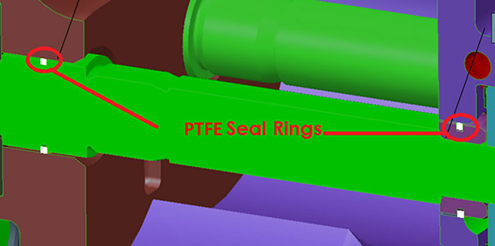 Image 5. PTFE seal rings used in early expander units
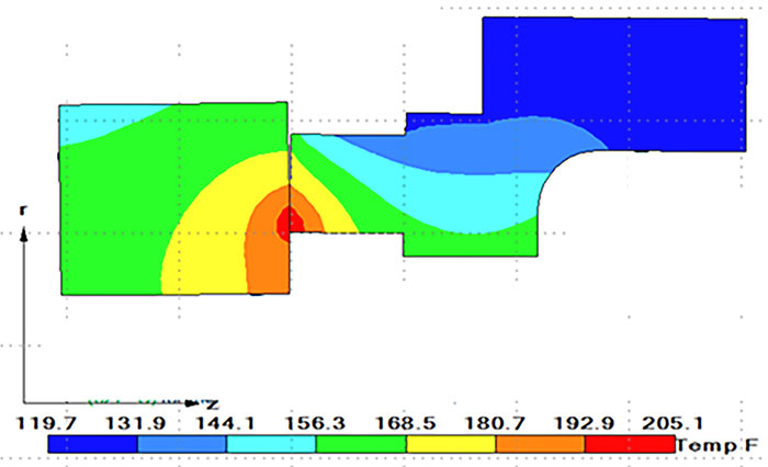 Image 6. FEA predicted results
- Predicted results show minimal leakage rates across the inboard seal faces, and show virtually zero leakage, meeting the strict leakage requirements of the application.
- FEA predictions for total deflection and temperature distribution for the process side seal subjected to the maximum conditions on one of the expander stages are acceptable and below limits of the materials involved.
- FEA predicted results for seal wear life exceeds minimum seal life requirements for the application even under maximum operating conditions.
- Double seal arrangement can operate without continuous supply of buffer media, which reduces operational cost.
- Seal cavity at the OD can be used to direct process media or oil leakage to separate outboard port for gas or liquid.
Dry Powder Ribbon Blenders
Dry powders can make sealing difficult for many reasons, primarily because an attempt to use sealing devices that contain or require wet lubricants often results in clogging of the powders in and around the sealing device. Depending on the type of powder being sealed, this can be catastrophic for the process, the sealing device and the equipment. Horizontal ribbon blenders are generally slow rotating with longer slender shafts than those used in pumps, which are typically sealed with mechanical seals. It is not uncommon to see these types of equipment sealed with traditional compression packing, as the perception is that the packing offers low cost, easy maintenance and relatively trouble-free operation at low speeds. To prevent the packing-to-shaft interface from directly contacting the powder, the packing is often flushed with nitrogen or compressed air. This should blow the powder away from the lubricant-impregnated packing and prevent clogging. Appropriate steps ensure the nitrogen or air used to flush the packing is itself not only clean and dry, but reliable. Any reduction of flow or pressure could allow the dry powder direct access to the packing-shaft interface. Split mechanical seals are an alternative to packing in dry powder ribbon blenders and can be operated without the need for flushing. Material advancements allow dry powders to be sealed effectively without concern of heat or degradation of the seal from penetration of the powder. A common means of improving load and wear of carbon/graphite mechanical seal faces has been to introduce metallic-based materials into the formulation.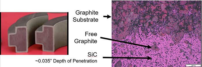 Image 7. Siliconized graphite face material structure