
A site visit and testing are critical to the process.
ProPump Services LLC
03/19/2018
The Environmental Protection Agency’s (EPA) 316b requires utilities to reduce condenser cooling water velocity at intake screens to mitigate the impact on aquatic life. For utilities, this affects primarily “once-through” circulating water systems, or units without cooling towers. For existing plants, there is considerable flexibility on a local basis to support practical and cost-effective solutions to strike a balance between environmental and plant economic issues.
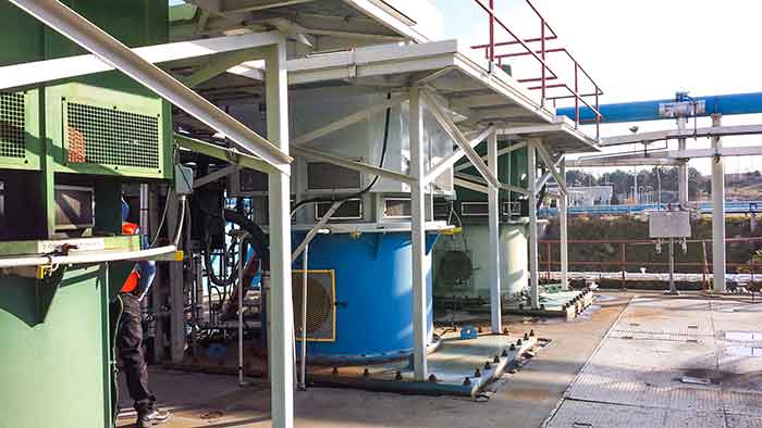 Image 1. Typical circulating water pump installation (Images courtesy of ProPump)
- Modify circulating water pump design or operations: Throttling pumps (see Image 1), running fewer pumps, rerating one or more pumps
- Incorporate variable speed drives (VSDs).
- Increase inlet screen area (see Image 2).
- Add a cooling tower.
- Combinations of the above solutions
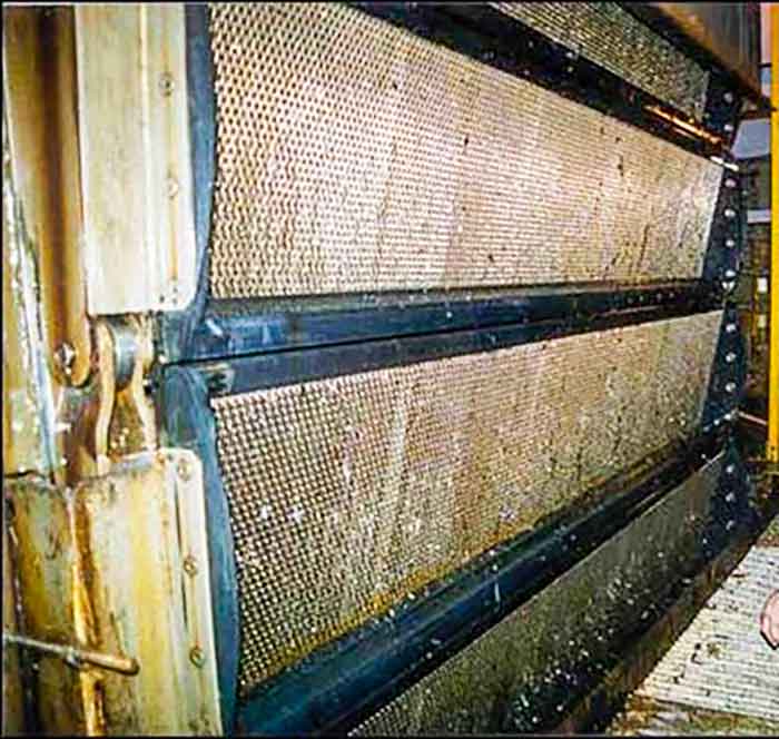 Image 2. Existing traveling screens
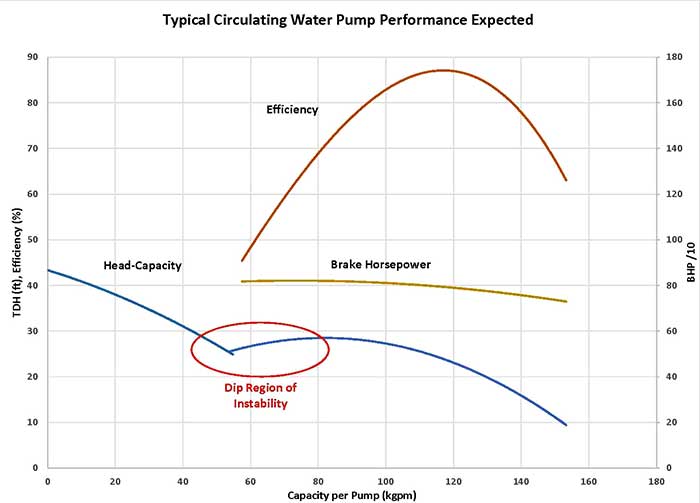 Image 3. “Dip” the head-capacity curve for low head pumps
 Typical inlet tip speed design values for circulating water pumps range from 50 to 85 feet per second (ft/sec), with the higher tip speeds requiring higher minimum flow rates to avoid damage. Any consideration of throttling for long periods needs to evaluate the inlet tip speed as well as other key factors. From involvement in various 316b system studies, some generalizations can be made.
Circulating Water Pumps
Many older systems lack “design basis” documents, such as pump curves, system resistance curves and hydraulic gradients. These are important for analysis and future plant needs and can be recreated as part of the testing program if missing. Most pumps were not designed for low flow operation (some performance curves do not even provide low capacity data, since it is not recommended to run the pumps there). Many pump curves are not completely accurate due to worn pump components, inaccurate original curve (often the dip area is misrepresented), or use of incorrect replacement hydraulic components. Circulating pumps used in parallel (most cases) must maintain the same rpm. If the system uses VSDs, they must be used on all pumps in a common unit and operate at nominally the same speed.Cooling Water System
Condensers are often running inefficiently and lack instrumentation to monitor and trend performance including cleanliness (increased pressure drop due to tube fouling), liquid level in water boxes and presence of vacuum leaks.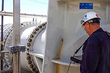 Image 4. Wetted vibration transducers provide vibration data below grade
Instrumentation
Flow metering can be difficult on once-through systems due to buried pipe, pipe materials (concrete or concrete lined) and lack of accessibility. Several intrusive and non-intrusive methods can be employed to provide adequate flow metering results. Circulating pump systems have minimal instrumentation, often lacking basis data such as:- discharge pressure
- intake water level
- vibration monitoring
- motor amps
- motor thrust bearing temperature
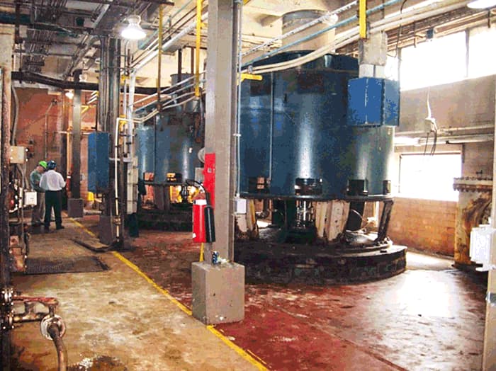 Image 5. Site walkdown and data collection
- Visit the site and conduct a system walkdown. Collect data, drawings, curves, etc. Discuss plant goals and constraints (see Image 5).
- Develop a test plan. Discuss testing plan with site personnel.
- Perform system testing. Collect flow and pressures including pump discharge pressures, condenser inlet and outlet pressures, motor data. (There are many options for flow metering to determine existing pump and system performance. If possible, non-intrusive flow metering is performed. If this is impractical, there are alternate testing means to determine system capacity.)
- Perform an analysis of data and issue report and conclusions.
- Present options and cost/benefit analysis.
