

It seems like everyone in the pump industry is jumping on the variable speed wagon these days. Are variable speed drives really the magic red pill for what ails pump systems? The answer is: It depends.
Variable speed applied to pumping systems will solve many problems from the perspective of energy savings, control management, reliability and reduced equipment wear. All of these elements add up to reducing the total cost of ownership (TCO) for the pump system.
Paradoxically, in the shadows there remain sinister pump boundaries and system limitations waiting to ruin the party, so variable speed may not be the panacea for all of your applications. The juxtaposition of the pump curve in its relation to the system curve must be a compatible match. Like a good marriage, they need to fit properly with each other.
When I started in the pump business, variable speed meant you were using a steam turbine or perhaps a hydraulic coupling to drive the pump, and both were expensive options with long intervals for return on investment (ROI).
Fast-forward to the present day, many of the early issues with variable speed drives (VSD) and the subset of variable frequency drives (VFD) now vanish in the rearview mirror. There are probably tens of thousands of successful applications in North America alone. For this column, we will focus on VFD applications.
Why Would You Want a Variable Speed Pump?
The most common reason to apply a VSD is that the pump is oversized for all or some of the system requirements. So, the pump output is either bypassed or throttled in some manner to keep the pump operation point away from the right end of the curve that is fraught with potential cavitation and related performance issues. Throttling or bypassing flow from the pump is inefficient and manifests as wasted energy.
Another reason for a VSD may be that the system’s operational needs are dynamic—as process conditions, loads and/or levels change, the pump operational condition requirements also change. One of the great applications for VFDs is on systems where multiple pumps are operating in parallel. The VFDs (by prudent incremental speed adjustments) can force the pumps to operate together satisfactorily in a system where they would normally fight for the hydraulic load.
The primary economical reason to install a VSD/VFD is energy savings, but it could also simply be to have soft start/stop ability to avoid rotor dynamic inertia and/or water hammer issues. VFDs offer the ability to operate three-phase motors on single-phase power—an important benefit in nonindustrial, rural and agricultural applications.
From the aspect of system control, VFDs “speak” digital and, thus, interface extremely well with computers’ (OS systems) electronic control circuits such as programmable logic control systems (PLCs), distributed control systems (DCS) and supervisory control and data acquisition (SCADA) systems.
Alternative Methods
In the interest of a more reliable and efficient pumping system, the VFD is likely the best and most efficient choice. But if the VFD is not the answer (for various reasons), the alternatives may include some of the following:
- Multiple speed motor-pump (close-coupled), normally only used on hydronic systems. Selection choice of three different speeds.
- Multiple pumps of the same or different size, either in parallel or series
- A subset of the above could be an arrangement of one large pump and one small pump, known as a “pony-pump” arrangement. The two pumps are not to be operated at the same time. These may be in series, parallel or series-parallel.
- Turning the pump on and off as required to control the process
- Throttle the pump discharge with two- or three-way control valves or simply a bypass to suction. A subset solution may be an orificed bypass.
- Hydraulic and magnetic couplings
- Belts and sheaves arrangement
- Alternate drives such as IC (internal combustion) engines, air (pneumatic) or hydraulic motors and steam turbines
Before You Buy a VSD/VFD
The suitability or fit of a VFD-driven pump into a given system with dynamic condition points (head and flow) is like a big jigsaw puzzle: You can’t force the pieces to fit, but when the parts do come together, it can form a real nice picture.
Before you decide to purchase the VFD system, first take a look at the pump duty cycle, the system requirements under all expected flow and pressure (head) conditions, the liquid properties (especially if slurry or suspended solids are involved), the geometry (shape), and the intersection points, of the pump and the system curves.
Also, be aware of the limits and boundaries of the pump, the motor, the drive and the system.
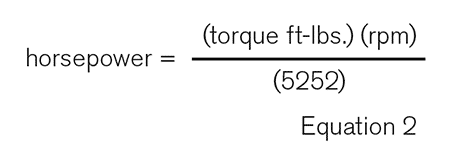
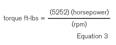
Motor: Speed, Efficiency, Horsepower & Torque
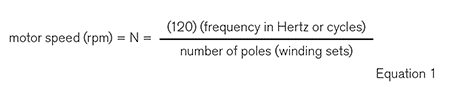
Motor speed is a function of the frequency (expressed in Hertz or cycles) of the alternating current (AC) electrical power supply and the number of motor poles (winding sets).
The number of winding sets is always an even number. For example, a two-pole induction motor on 60-cycle power will operate at speeds just under 3,600 revolutions per minute (rpm), typically a nominal 3,550 rpm.
The synchronous speed would be 3,600 rpm, but since the vast majority of industrial motors are the asynchronous induction type—in lieu of synchronous—there is inherent “rotor slip.”
Consequently, the motor operates at a slightly slower speed, normally at 2% to 5% less. Motor efficiency diminishes dramatically at speeds less than 60% of the base speed.
To prevent operating the motor in this inefficient range, an operational guideline may be enacted and placed in the control logic to avoid operating the motor at less than 50% of full load. Beware of the required horsepower (hp) and/or torque as you adjust speed, because at some point you may not have enough of one or the other.
Pump Affinity Laws
Pump performance varies with speed. It is important to understand that three of the functions change in vastly different ways with the speed changes.
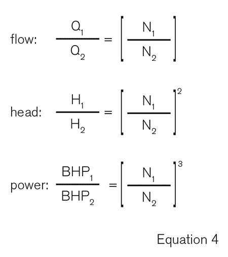
Flow rate varies directly with speed changes. That is, if the speed is increased or decreased, the flow rate changes in linear proportion. The head varies by the speed ratio squared. The power required varies by the speed ratio cubed.
The affinity laws are applicable for small changes in speed, and note that the system curve still dictates where the pump will operate.
Notice that a small change in speed has a big effect on power (cube function), and this is one of the main reasons why VFDs are so popular. I suggest that you use the variable speed curves from the pump manufacturer and use the affinity laws only to understand the function and for estimates.
Affinity laws: where Q = flow, H = head, BHP = brake horsepower, and N= speed.
For impeller diameter changes on the pump, the diameter ratios follow similar affinity rules as the speed ratios. A change in diameter ratio will have a direct effect on the flow rate.
The head will be affected by the diameter ratio squared and the power will be affected by the diameter ratio cubed. The formulas are the same as above except substitute diameter (D) for speed (N) in the equation.
Similar to the affinity “laws,” these thumb rules are just meant for small changes. Note that the more an impeller diameter is changed from the maximum diameter, the less-accurate the relationship.
I suggest, if at all possible, using the maximum-size impeller for the VFD-driven pump to better preserve efficiency at all selected speeds, except perhaps if you will be over-speeding the pump where inertia issues may surface.
Read more Common Pumping Mistakes articles here.
