
High flow operation among root causes.
Saudi Aramco
04/23/2019
Two shaft failure investigations for two identical water injection pumps that had been commissioned for nine years showed that the main contributors to these two failures were a manufacturing error and operation well above the best efficiency point (BEP). Operating the pumps at 125 percent of its BEP for long durations resulted in wear to the system. One failed shaft was also investigated, showing rotating bending fatigue to be the mode of failure. Here are the findings and analysis that show how investigators reached these conclusions.
Introduction
The investigation was held at two salt water disposal pumps at a national petroleum and natural gas company plant in Saudi Arabia. The pumps are used to dispose of brine water produced at the gas-oil separation plant (GOSP) by reinjecting it back to the reservoir.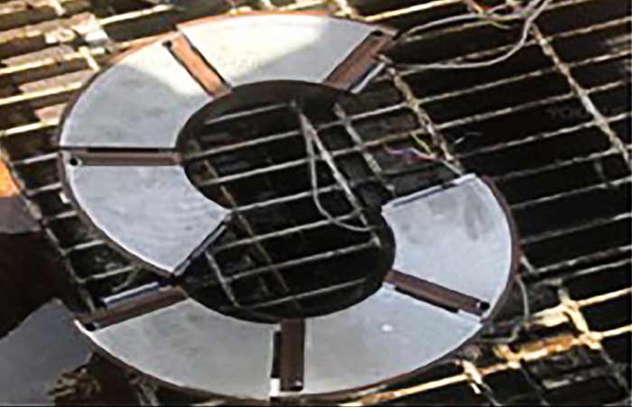 Image 1. Kingsbury LEG thrust bearing. (Images courtesy of Saudi Aramco)
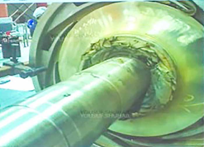 Image 2. Pipi Coating failure stuck in an impeller
The First Pump
On October 2017, the pump tripped on high outboard bearing radial vibration. At the site inspection, the following observations were made:- The pump was operating at a high flow rate, reaching 125 percent BEP for a long time.
- Excessive leakage was coming from the outboard mechanical seal.
- Oil leakage was coming from the outboard bearing.
- The vibrational data was collected and analyzed to identify the potential causes of the vibration.
- The vibration data showed a possibility of having internal misalignment, and the waterfall plot showed mainly 2X excitation.
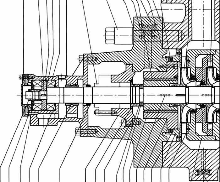
 3a and b. Shaft cut location
- Shaft was found cut at the thrust collar location, as shown in Images 3a and 3b.
- A nondrive end (NDE) mechanical seal was found to be overheated due to high axial movement after the shaft was cut.
- Active thrust bearing pads were found with minor rubbing marks.
- A thrust collar washer (between shaft shoulder and thrust collar), Image 4, was found with rubbing marks. In addition, it had uneven thickness. This uneven thickness caused the thrust collar not to set square with the shaft and resulted in a cyclic loading on the shaft.
- A nonactive thrust bearing was found to be in good condition.
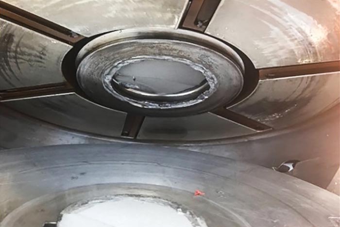 Image 4. Thrust collar washer
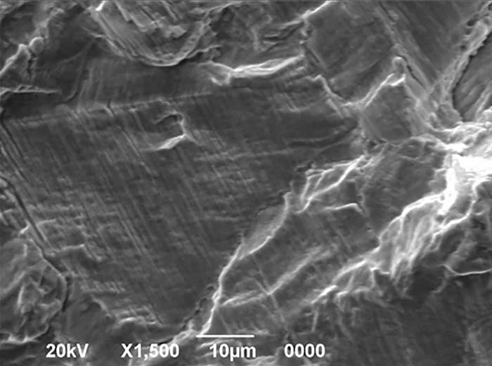 Image 5. Scanned striation
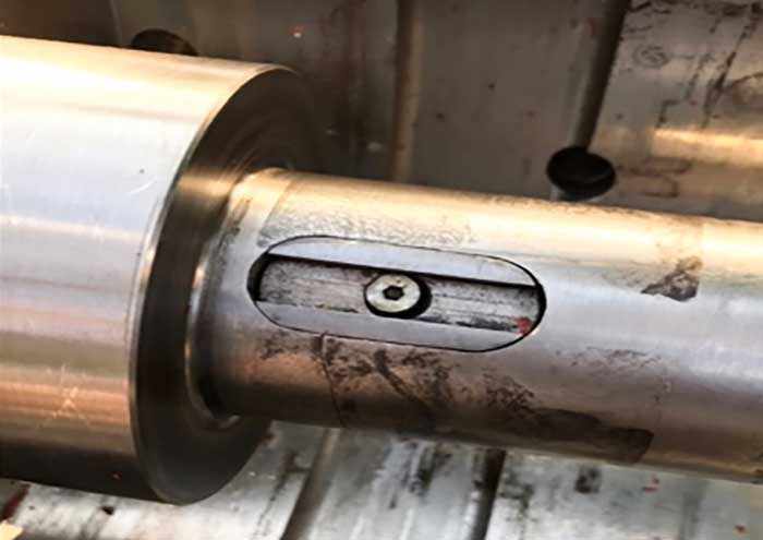
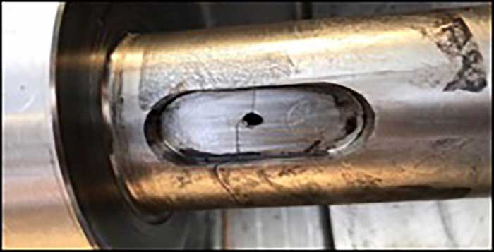
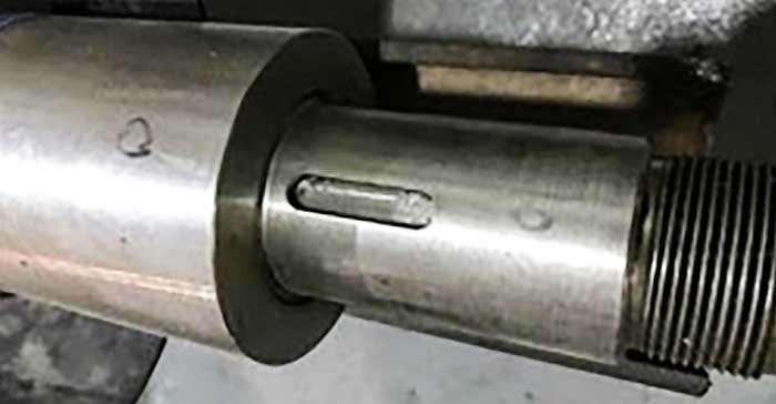 Image 6 (top to bottom). Fabricated key slot with the securing screw showing shaft crack. Image 7. Key slot removed and inspected. Crack shown to be initiated at the screw location. Image 8. Normal key slot design of identical pump without key slot insert.
The Second Pump
This pump experienced high drive end (DE) and NDE mechanical seal leakage. Mechanical seals were replaced, and the machine was returned to service. However, the pump tripped due to high axial displacement. The shaft axial float was adjusted and the pump started, but it tripped again for the same reason. The NDE bearing housing was removed and the shaft was found cracked under the thrust collar key area. The shaft key slot had an insert that was added due to a manufacturing error. This insert was fixed to the shaft by a screw to correct the keyway (Images 6 and 7). This design mandated a threaded hole in the shaft, which acted as a stress riser and caused the initiation of the shaft crack. Image 7 shows a normal key slot for the other pumps that did not suffer from this manufacturing error (i.e., no insert). In addition, a thrust collar locknut was found loose, which could have been a contributing factor. The thrust collar experienced minor rubbing marks indicating rubbing with the thrust collar washer. Further inspections tested the stability of the thrust collar assembly. Measurements were taken for the shaft diameter and the thrust collar inner diameter. The clearance was found to be 0.004 inch, which is high compared to other sister pumps (0.001 inch). This high clearance contributed to the failure since it will not allow the thrust collar to set correctly and causes a rocking action, increasing the forces on the shaft.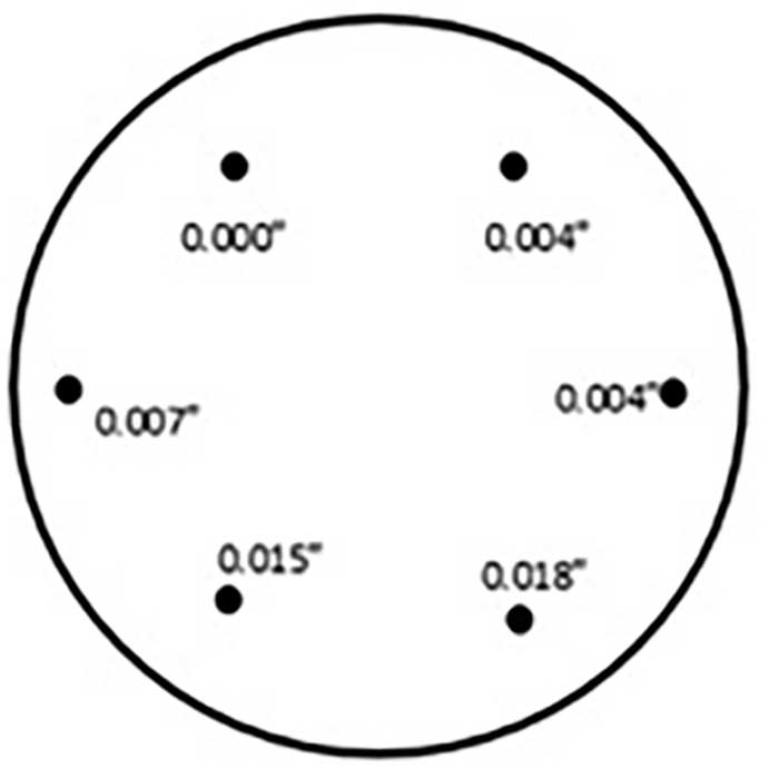 Image 9. Face runout readings collected on thrust collar
Corrective Actions
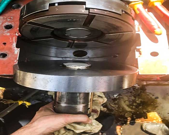
Both shafts were repaired by a stubbing method. The national petroleum and natural gas company used old Inconel 625 shafts from other pumps to make two small stub shafts. The pump damaged shaft was cut, drilled and threaded to add a new stub shaft section. Once the new sections were in place, the shafts were welded together to form a new shaft. The new section was machined to tolerance to ensure proper fit and acceptable shaft runout (Image 10). The pump was put back into service with no issues.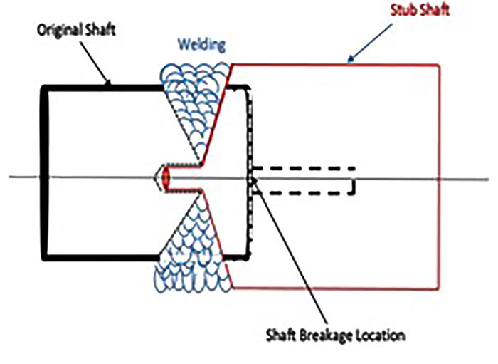 Image 10. Shaft stub method