
Heavy, salty pumped fluids can be sealed with a water and buffer system.
10/22/2013
For a process pump in which liquids with chemical contents are pumped, damage to the seal can occur. The chemicals may cause damage on a standard seal. In many of these applications, a water-lubricated lip seal may eliminate this kind of damage.
Basic Functions Within a Lip Seal
Initially designed for heavy-duty dredging pumps, the lip seal is a water-lubricated shaft seal, which is best suited for pumps that process fluids containing abrasive particles or particles that are larger than 100 micrometers. This lip seal is designed to be lubricated with an external flushing water supply (up to 40 bar) that is reduced to almost atmospheric pressure by the seal itself. This lip seal is made of independently operating modules, each fulfilling a function. The basic functions are:- Sealing
- Dirt retaining
- Pressure reduction
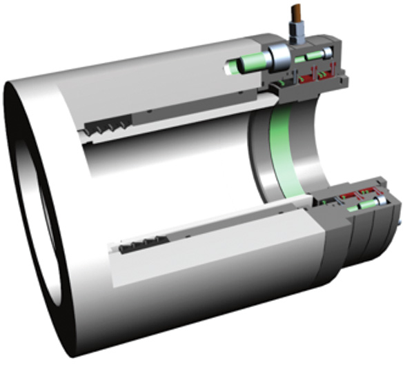 A section of an engineered design of the water-lubricated process pump sealing solution
Case Study: Paint & Coatings Company
A European paints and coatings company encountered continuous major problems with packing seals on its salt production, circulation axial-flow pumps. They wanted to maintain a MTBM of six years, because that would coincide with the main maintenance interval of the pumps. The friction caused by the salt and water resulted in damage to the pump seal that was installed on these pumps.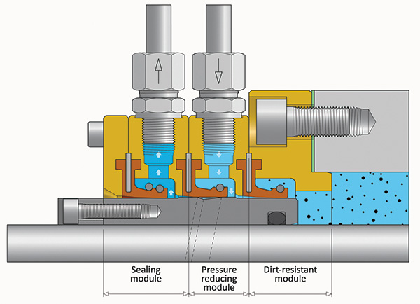 The water-lubricated lip seal