
The addition of five new styles of rubber expansion joints (REJs) within the Fluid Sealing Association (FSA) technical handbook has increased the opportunities for the selection and application of REJs. Similar styles can be found in the metal expansion joint standards of the Expansion Joint Manufacturers Association (EJMA), but these styles were not previously available within the REJ standards published by FSA. The previous standards focused primarily on unrestrained REJs installed in an anchored and well-guided piping system. The five new styles of REJs include universal, hinge, gimbal, in-line pressure-balanced and elbow pressure-balanced. They all incorporate a restrained design, which manages pressure thrust forces in the piping system. The selection and application of these REJ categories are particularly useful in systems that have support structures or adjacent equipment with load limitations. All REJ styles can absorb set movements, reduce noise and vibration, have a cycle life in the tens of millions, compensate for misalignments, provide access to piping and equipment, and relieve pipe and anchor stresses. When any REJ absorbs fluctuating thermal or external movements in ridged piping systems, they replace or exchange the catastrophic effects of these stresses with the inherently low stiffness or spring rate of the REJ. Unrestrained REJs, which were covered by the previous standards, are designed to absorb all directional movements in well-anchored and guided piping systems. Their spool-type body is often constructed with full-rubber flanges, a high-grade, leak-proof tube, multiple layers of high-strength tire cord, high-tensile steel reinforcement, a seamless cover and galvanized retaining rings. The above construction, as a standalone expansion joint, represents the most cost-effective arrangement when used in rigid-piping systems with main anchors (MA) and numerous guides at specific spacing. Control units can be externally or internally attached and used as limit rods for secondary restraint or as tie rods when the support structure or adjacent equipment have load limitations. The five new styles of REJs covered in the FSA technical handbook are outlined below.
1
Universal rubber expansion joints feature two resilient arch sections separated by a straight section to facilitate greater lateral-movement capability. This single-unit arrangement represents an effective solution for absorbing axial thermal movements from adjacent pipe runs. Its spool-type body is often constructed with full rubber flanges; a high-grade, leak-proof tube; multiple layers of high-strength tire cord; high-tensile steel reinforcement; a seamless cover and galvanized retaining rings. Their control units are externally or internally attached and used as limit rods for secondary restraint in a properly anchored piping system, or as tie rods when the support structure or adjacent equipment have load limitations.2
Hinge rubber expansion joints are designed to facilitate and isolate angular rotation in one plane. The arrangement consists of a pair of hinge plates connected with pins and attached to the expansion joint's external or internal hardware. The hinge assembly must be designed for the internal pressure thrust forces of the system. These REJs can be used in sets of two or three to absorb large lateral movements in a single plane. This optimally designed arrangement is an effective solution for absorbing large axial thermal movements from an adjacent pipe run. Its spool-type body is often constructed with full rubber flanges; a high-grade, leak-proof tube; multiple layers of high-strength tire cord; high-tensile steel reinforcement and a seamless cover. It is commonly used when the support structure or adjacent equipment have load limitations. The economic benefits of this arrangement include a smaller system footprint with far fewer anchors and guides.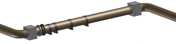 Figure 1. Unrestrained REJ in straight-anchored and well-guided pipe run (Graphics courtesy of the Fluid Sealing Association)
 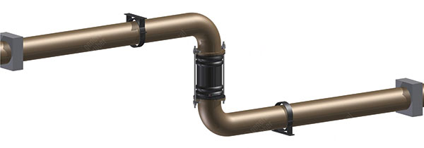 Figure 2. Universal REJ in a single-plane, Z-shaped pipe run
3
Gimbal rubber expansion joints are designed to facilitate and isolate angular rotation in two planes. The arrangement consists of two pairs of hinge plates connected with pins to a common gimbal ring and attached to the expansion joint's external or internal hardware. The gimbal assembly must be designed for the internal pressure thrust forces of the system. They can be used in sets of two or sets of two with a single-hinge design to absorb large lateral movements in multiple planes.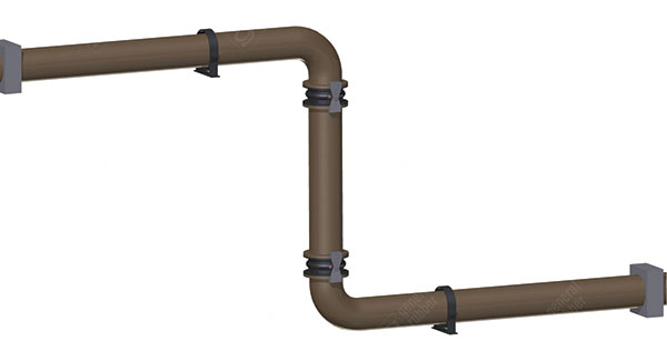 Figure 3. Two-hinge REJs in a single-plane, Z-shaped pipe run
4
In-line pressure-balanced rubber expansion joints provide the only effective solution for directly absorbing large axial thermal movements while continuously self-restraining the pressure thrust forces. This arrangement consists of tie devices interconnecting the main joint sections to the opposing balancing joint section and is commonly used when the support structure or adjacent equipment have load limitations. The body is often a one-piece rubber construction with full rubber flanges; a high-grade, leak-proof tube; multiple layers of high-strength tire cord; high-tensile steel reinforcement; a seamless cover and galvanized retaining rings. The economic benefits of using pressure-balanced designs include a smaller system footprint as well as far fewer guides, anchors and supports.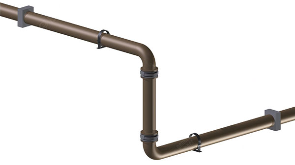 Figure 4. Two gimbal REJs in a multiple-plane, Z-shaped pipe run
5
Elbow pressure-balanced rubber expansion joints are designed to absorb all directional movement while continuously self-restraining the pressure thrust forces. This consists of tie devices interconnecting its main joint section to its opposing balancing joint section and is often used when the support structure or adjacent equipment have load limitations. The pair of spool-type bodies are often constructed with full rubber flanges; high-grade, leak-proof tubes; multiple layers of high-strength tire cord; high-tensile steel reinforcements; seamless covers and galvanized retaining rings. The economic benefits of using pressure-balanced designs include a smaller system footprint as well as far fewer guides, anchors and supports.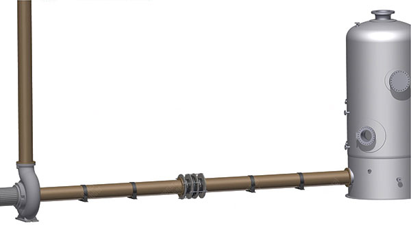 Figure 5. In-line pressure-balanced REJ in straight pipe run with load limitations
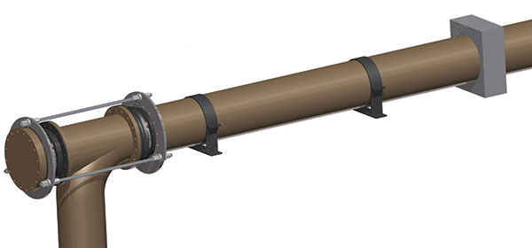 Figure 6. Elbow pressure-balanced REJ in a single-plane, L-shaped pipe run with load limitations
- Capabilities and limitations of different anchor types including main, directional or intermediate
- Piping codes i.e., American Society of Mechanical Engineers (ASME) B31.1, ASME B31.3 or others
- Location of various equipment, branch connections and space restrictions
- Capabilities of support structures and load limitations on piping and equipment
- Operating conditions including, but not limited to, temperature and pressure
- Amount of thermal and/or external movements anticipated
- Need to absorb noise and vibration
- Need to compensate for misalignment
- Need to provide access to piping and equipment
- Need to absorb shock loads and required cycle life
- Capabilities and limitations of different REJ styles including unrestrained and restrained arrangements
