

One calculation that is important in pump system design is calculating the head required by the pump, which includes static head and frictional head losses. A primary consideration in the frictional head loss is the friction associated with fluid flowing through pipes. These kinds of losses are referred to as major losses, while losses due to fittings and valves are referred to as minor losses.
Major losses can be calculated using the Darcy-Weisbach friction factor (f), which is a function of the pipe absolute roughness, inside diameter and the Reynolds number (Re). The Colebrook equation (Equation 1) defines this relationship implicitly, which means that f must be calculated by plugging in values of f and comparing the left- and right-hand sides of the equation. It is important to note that Equation 1 is typically used for turbulent flow (Re>4,000) and using it in the transition zone between laminar and turbulent flow regimes will result in greater error. Refer to the Hydraulic Institute (HI) Data Tool and the Moody diagram for laminar and transition flow regimes.
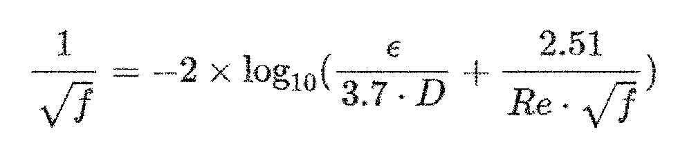
This method can be solved using a programming language by iterating the value of f and using logic statements to compare each side of the equation. It can also be done in Excel with one column for the f value and another two columns for each side of the implicit Equation 1. The f value would be the one that results in the right-hand side and left-hand side being approximately equal.
Two other ways to determine the f are:
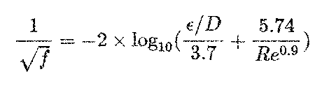
- By using an explicit form of the Colebrook equation (Equation 2) with variables as defined in Equation 1
- By using a Moody diagram
The explicit form of the Colebrook equation shown in Equation 2 is slightly less accurate than the implicit Equation 1 but can be solved by plugging in the absolute roughness, the Re and the pipe inside diameter of the pipe, and it can be solved without iteration. The Moody diagram can be found on the HI Data Tool website and is a graphical representation of f as a function of Reynolds number and relative roughness.
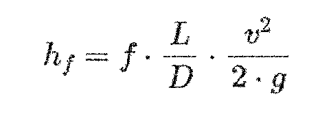
After determining f, the major losses can be calculated by Equation 3, which is a function of the f, pipe length, pipe inside diameter and velocity. Note that if there were multiple pipes of differing inside diameters and flow velocities, they would all need to be considered separately and summed together to get the total major losses.
To simplify the calculation process, use the HI Data Tool pipe friction loss calculator, which utilizes the Colebrook equation as described in Equation 1. The calculator simplifies the process by allowing the user to select the standard pipe size and input the flow rate and pipe length, and it also assigns a typical absolute roughness and then calculates the remaining values and frictional head loss.
