

Pump folks are typically used to dealing with liquids, and the main tool in their toolbox is hydraulics. From the flange of a pump out is what we consider a hydraulic system. A pump curve intersects a system curve, and that is where the pump will be forced to operate.
But consider pumps’ close cousins: fans and compressors. They work similarly, pushing fluid forward. But for them, fluid is not necessarily liquid—it may be liquid, vapor (gas) or anything in between. The good old thermodynamics that we left long behind us as something we touched on in school and something too complicated for our liquid world. Enthalpy, entropy, phase diagrams and similar fancy words are rarely used in our pump world. Bernoulli is perhaps as far as we would go regarding science—even reluctantly if push comes to shove.
In this article, I wanted to take a different look at the world of blowers and compressors in a simplified way without getting into the nightmare of theoretical equations and derivations, most of which would probably put you to sleep before you even got to the middle of the story.
And so, take a look at an interesting case—one hopefully practical and useful to you as it may shed new light on work problems as well as issues of practical importance you might have at home.
Consider a case of a system misbehaving with your air conditioning at home. To explain simply, an air conditioning system consists of inner and outer units. The inner one hangs in your living room (and/or other rooms), and the outer unit, housing a compressor and expander, sits outside. This is either attached to an outside wall of an apartment or sitting on the ground outside a house. Such systems are simple but have some difficulties to maintain, such as recharging freon, as their access can be a challenge. One example is if the unit hangs outside of a 10th-floor apartment.
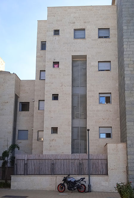
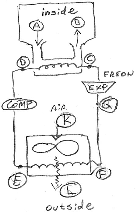
A more modern way to handle this, particularly for the new apartment building projects, is to build the apartment(s) with a niche: a relatively small service room outside of the apartment with a door for ease of access and maintenance. A hot water boiler might also be positioned there instead of sitting on the roof of the building, thus easy to reach and repair if needed. A simplified diagram of the home heating, ventilation and air conditioning (HVAC) unit is shown in Image 3.
From inside of your house, the warm air you want to cool enters the inner unit of the air conditioner (Point A). Blown by the fan (not shown), it passes by the cold coils containing freon (gaseous, as it was expanded by the expander). Air is cooled by freon and exits to the room (Point B) cooler—say 70 F, or whatever temperature your thermostat is set at.
Freon receives the energy (heat) of the air, which warms it from approximately 11 C (50 F, Point C) to 12 C (53 F), and the small temperature change is because of the significant heat absorption and mass flow of freon. The warmer freon gets picked up by the compressor, which turns it at high pressure back to liquid (Point E) and makes it much hotter (~200 F). Liquid freon then passes through the outside heat exchanger (from Points E to F) getting cooled by a fan, which blows air from Point K to Point L.
A cooler freon then continues to the expander (Entrance G), making it a vaporous state again and cold, exiting at Point C. The cycle repeats, continually making the room air cooler and cooler.
We will now connect the dots to our pump world: let’s use the fan of the outside unit as our pump, and its system is the surrounding air in the auxiliary room where it sits. The specific speed (Ns) is high for the fans as compared to the pumps because fans generate a low head (differential pressure is tiny).1 The system now has an added aspect of being gas, and it also has an important aspect of thermal behavior.
Clearly, the inlet side of the fan should be as cool as possible, and during a hot summer, it makes it more difficult to cool the freon. But as long as the blower sits in an open unobstructed space, it is cooled reasonably well and hopefully helped by shade or wind, etc. But if you were to put this unit inside a space where the air is stagnant and cannot be easily moved out to cool the coils, you would have a problem.
So was the case here. I did a 24-hour test of my HVAC unit, as it sits in a space convenient for access but otherwise essentially a dead space of a cement box, surrounding the unit from five sides. The only open side is where the poor struggling fans need to blow hot air out, and it is the same space from where a cooler, ambient air needs to get in. Thus, circulation in my example is badly restricted—a poorly designed system.
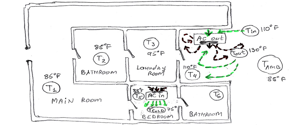
Starting early in the morning, I measured the temperatures of all rooms and all points as noted in Image 4. I used a laser point thermal gun to read the temperature of the room wall so it is not exactly the same as the temperature of the air in a room. But, over a long test, it would show a trend of changing thermodynamics of the struggling system we have.
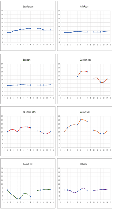
As you can see from Image 5, initially everything is roughly at the same temperature, due to a cooling night effect. But as the day goes on and it gets hotter, the AC kicks in and tries to cool the bedroom—the object of the test. Initially, the bedroom air gets cooler quickly, while the walls drop their temperature much slower, due to the retention of heat by their mass. But as time goes on, the temperature (as noted by the wall temperature) reverses and begins to rise, despite the AC continuing to struggle to cool it. Why?
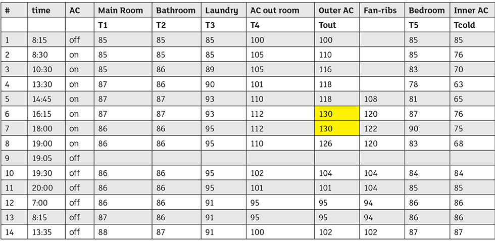
If you examine Image 4 showing the peak of the temperature rise in the auxiliary room (130 F), you will see how restrictive and inefficient its circulation is. The hot air tries to escape through the same open space through which the colder ambient air needs to enter, thus fighting each other, causing turbulent circles and a very poor cooling environment. The air entering the fan becomes hotter and hotter and exits the fan at an even higher temperature. Thus, the system is “stuck”—it chokes the fan from its ability to move its air outside the “cement straitjacket.”
After several hours, the auxiliary room (the outside unit site) becomes very hot and no longer allows the fan to cool the coils. Stagnant eddy circuits prevent good circulation, and the cooling effect essentially no longer works properly.
The good news is that everything has a solution, but the trick is to find a quick, inexpensive one instead of redesigning everything from scratch, which is expensive and not practical.
A question to you: What would be your proposed solution?
Let us know. We will share your answers with our readers, as well as the solution we applied.
References
Nelik, L., “Pumps and Pumping Systems Made Easy and Fun,” Volumes 1 (“A Bedside Companion”), 2 (“For the Perplexed”) and 3 (“For Those Who Still Would not Quit”), published by World of Ideas, Inc., 2022
Read part 2 here.
