

In the September issue of Pumps & Systems, we discussed how pumps’ close cousins—fans—can cause problems when improperly installed in a system (refer to the illustration of the system and sketches/graphs in that article).
The orientation of the cooling fan installed in the house auxiliary room caused the hot air (which got hot by removing heat from the compressed freon) to be trapped inside the room, not allowing the cooler outside air to reach the inlet of the fan properly. Over time, the air in the room would become hotter and hotter, eventually beginning to impact the heat transfer operation of the entire air conditioning (AC) unit, causing even the air in the main room to rise in temperature—after the brief period of initial cooling. Proper positioning of the fan would directly discharge the hot air to the room opening and allow space for cooler outside air to enter and reach the inlet to the fan properly.
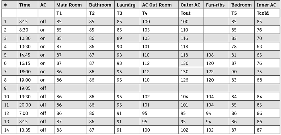
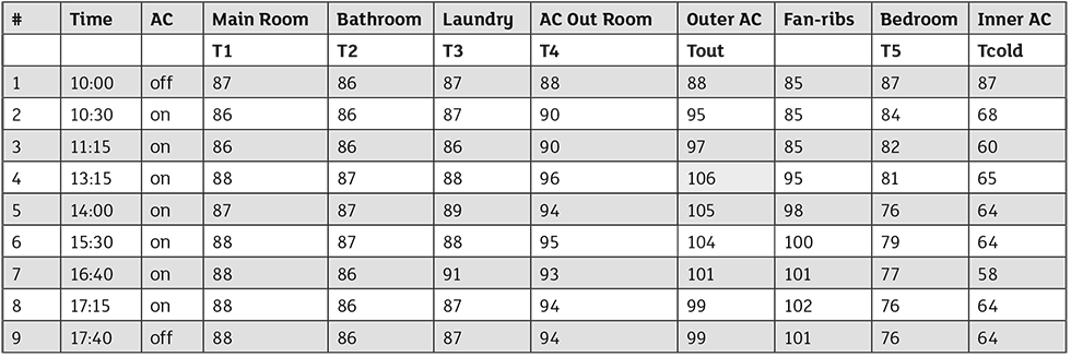
Image 2 is similar to a table presented for the test of the original situation in the September issue and shows that from the start of the test, all temperatures inside the house’s rooms stayed relatively the same, indicating that the AC unit now, operated properly, maintained the desired cold setting. Of primary interest is a comparison between the temperature trend over time in the auxiliary room where the fan unit was axially installed (noted in the table as “AC outer room”).
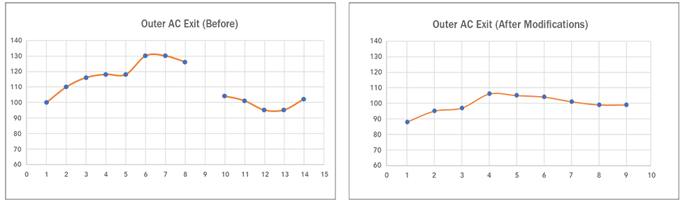
In the first test (improper position of the fan), the temperature rose from 100 F to 130 F (a 30 F difference), and in the modified configuration test, it went up from approximately 89 F to 105 F (a 15 F difference)—i.e., halved.
Note: The reason for the different starting temperatures (100 F versus 89 F) is due to different outside ambient temperatures between the tests, 92 F in the first test and 77 F in the second test, i.e., roughly in the right proportion.
In summary, it is clear that an improper installation of the outside unit of the AC system can cause a big problem. In a particular case tested, the temperature of the air surrounding the unit was dropped by approximately 15 F by modifying the installation in a
proper manner.
An interesting challenge is now presented, particularly to those familiar with computational fluid dynamics (CFD) computer simulation programs, such as SolidWorks, ANSYS, or similar programs. Assuming the room where the outside fan is installed has five enclosed walks and one fully open, with a room sectional area of 1.5 x 1.5 meters and 3 meters in height, analyze the flow patterns and heat transfer of this 4 kW fan, blowing air through the fan’s 60 cm opening. The fan blows air across the 100 C (roughly 210 F) coils from which the heat is transferred to the air, and the outside ambient temperature is 30 C (roughly 90 F). Feel free to make other simplifying assumptions as far as distances, etc. For example, you can make rough assumptions of the flow rate from the fan, based on its diameter, power and whatever knowledge you might have about typical fans.
Your mission, should you choose to accept it, is to do a simplified CFD analysis of the flow pattern, to demonstrate the circulation pattern of stagnant air in the first case as well as proper removal to the outside after modification. Then, do a (simplified) heat balance analysis, to show the temperature rise (or a lack of) in the room, compared to these cases.
Your solution will be represented in a future issue of Pumps & Systems, and you will also receive a free ticket to attend a Pump School Basics virtual session, coming later this year.
