Pumps can last for decades when operated correctly.
by Jim Elsey

I wrote a detailed article on minimum flow for the Pumps & Systems November 2015 issue (read it here). That article focused more on calculating the actual minimum flow boundaries than discussing the allowable and/or preferred operating regions and the resulting effects on pump reliability. Since then, the subject of allowable minimum flow limits for pumps and the consequential system reliability has surfaced on a regular basis in my work with owners and operators across the world. I constantly witness pump operators making poor decisions based on erroneous and/or partial data.

I frequently witness end users operating pumps at or near the shutoff point with little concern for the pump reliability and mechanical seal life. However, in a recent case the customer was looking at a pump reliability chart and interpreted the data from the opposite perspective, thinking they could only operate at best efficiency point (BEP). The subject chart created from a generic approach captured the prevailing pump issues that will occur when operating at points away from BEP. I will state that the chart is a good example to educate end users on the issues associated with operating away from BEP. A similar chart is shown as Figure 1.

pump reliability curve
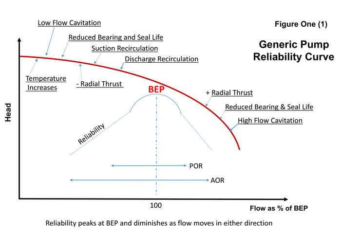
Figure 1. Generic pump reliability curve (Images courtesy of the author)

This chart is a great visual tool from a collective and generic prospective, but it does not differentiate for specifics such as pump size/geometry, shaft defection ratios, net positive suction head (NPSH) margin, specific speed (NS), operating speed, brake horsepower (bhp), operating temperature, fluid properties and suction energy (SE).

The customer was rightfully concerned that they are operating at a point away from BEP, but not too close to the minimum flow boundary. This month, I intend to use a small American National Standards Institute (ANSI) pump as an example to illustrate that most centrifugal pumps can offer satisfactory service when operated away from the design point, as long as the owner realizes there are caveats and boundaries.

My opinion is that a standard ANSI pump from a reputable manufacturer if selected, installed, maintained and operated correctly, will offer at least 20 years of satisfactory service based on industry average duty cycles, fluid properties and typical applications. While I have seen many ANSI pumps celebrate their 40th birthday in full service and still going strong, I have also seen pumps destroyed in minutes. Customers’ actual results will vary significantly based on a long list of parameters that affect the life and reliability of the pump that the end user controls in situ.

General Pump Design

All commercial and industrial centrifugal pumps are designed for one set of hydraulic conditions of head and flow, known as BEP. Other operating conditions of head and flow are a financial compromise.

At BEP, the pump will be at the most hydraulically efficient operating point, at the lowest disc friction and shock losses point, at the quietest point, at the minimum vibration point and at the least radial thrust point.

Thermal & Mechanical Minimum Flow

When determining minimum acceptable flow for a given pump there are several considerations. The first two are thermal limits and mechanical limits. How to calculate and assess these boundaries is covered in my earlier article from November 2015.

The main point of this current article is to discuss the operating range between BEP and minimum continuous stable flow (MCSF). MCSF is the minimum flow that must be maintained through a pump to avoid excessive recirculation at the impeller inlet.

Mitigating Factors in the Evaluation of Minimum Flow

Specifications and design:
Hydraulic Institute (HI)/ANSI B73.1 overall operating parameter specifications and subsequent manufacturing designs are more liberal for the ANSI B73.1 pumps in general than American Petroleum Institute (API) 610 pumps as a comparison. The difference is mostly due to the amount of energy involved for typical applications (measured predominantly as horsepower [hp] or kilowatts [kW], but not totally). Additionally, there is an API 610 specification parameter that mandates a minimum 3-year continuous operation no matter the operating conditions. API pumps are comparatively in an advanced league. Applications for API 610 pumps include a significantly wider hydraulic range, higher temperatures and higher pressures than required in the ANSI B73.1 applications.

An API 610 compliant pump is always going to be markedly more expensive than an ANSI pump of similar size; it is therefore prudent to protect the investment. API pumps are typically in processes that have little to zero tolerance for unscheduled shutdowns due to the extremely high cost. For the particular example in this article: the ANSI B73.1 minimum flow specifications for the pump in question (ANSI - AA) (1 x 1.5 – 6) call for a minimum continuous flow of 15 gallons per minute (gpm) based on operating with the maximum impeller diameter. The impeller in this case was trimmed to 4.25 inches, which is approximately 75 percent of the maximum diameter; consequently minimum flow for this application can be as low as 12 gpm. The end user operates the pump at 30 gpm.

Suction specific speed:
As suction specific speed (NSS) decreases, the requirement for minimum flow can also be relaxed. The NSS for the example impeller is 7223 (based on U.S. Customary Units [USCU]) which is well below any normal concerns that designers express. Normally pumps with NSS approaching 11,000 are a concern for applications at low minimum flows due to suction recirculation issues. Refer to published technical papers by Simon Bradshaw and Jerry L. Hallam for more information on this subject. Due to the lower suction specific speed for the example pump, the minimum flow concern can be relaxed.

vane overlap
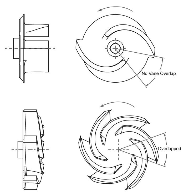
Figure 2. Example with no vane overlap (above) and with vane overlap (below)

Impeller vane overlap:
The example pump has a five-vane semi-open impeller. See Figure 2 for an example of vane overlap. On a design scale, the vane overlap on this impeller is high and thus mitigates potential issues with recirculation. Impellers with lower vane overlap will facilitate discharge pressure to recirculate flow back to the suction due to less interference from the vanes. If your pump has little to no vane overlap, add that mitigating component to your reliability equation.

In this case, the vane overlap mitigates issues with operation to the left of BEP. Note that many services, such as slurry and trash applications, require impellers be designed with little to no overlap.

Impeller inertia:
Because of the small size and weight of the example impeller, it will contribute lower radial forces on the rotor dynamics. It follows intuitively that an impeller weighing 100 pounds will have more effect than one that weighs five pounds. While I cannot offer an actual reliability formula, in this case the impeller weight would be a direct relation.

Overall impeller-to-eye diameter ratio, or D1 to D2:
The ratio of the overall diameter of the maximum impeller size compared to the diameter of the inlet eye may sometimes be a concern. Note this ratio is directly related to NSS (refer to NSS technical papers).

The example impeller is of little concern. The overall maximum diameter (D2 dimension) is 6.0625 inches and the eye (D1 dimension) is 3.14 inches.

In summary, the larger the suction eye is in relation to the overall diameter, the more likely there will be an issue with recirculation at lower flows.

Specific speed:
Specific speed (NS) is a mathematical expression for the overall geometry of the impeller. In this particular instance, there is a five-bladed impeller and we are looking for a curve shape that has a continuous rise to shutoff as the curve moves right to left from the BEP design flow point back to shut-off (zero flow).

By virtue of the curve shape and the anticipated intersection of the example system curve to the pump curve, this shape indicates that the pump will not hunt or oscillate at the low flows approaching minimum flow and shutoff.

NPSH margin, fluid temperature and vapor pressure:
Another guideline is the net positive suction head (NPSH) margin (NPSH available as compared to NPSH required). The higher the margin, the more stable the pump will be at low flows. This is partially due to the fluid’s initial temperatures and subsequent temperature increases (delta T) that can occur when the fluid is recirculating at the suction eye and nearby impeller blade edges. As the fluid temperature increases, the corresponding vapor pressure will also increase to the point of cavitation bubble formation and subsequent collapse causing vibration/shock and erosion.

The lower the fluid temperature and the higher the NPSH margin, the more stable the pump will be at the lower flows and approaching minimum flow.

Shaft stiffness/deflection ratio:
While not an option in this example due to the fluid’s acidic properties, the use of a solid shaft would reduce the shaft deflection ratio (L3/D4) from 143 to 64. Shaft deflection ratio should be one of the major components in the equation for pump reliability at low flows. From the mathematical formula aspect, keep in mind the reverse (indirect) relationship. The lower the number, the better.

Design to counter deflection due to unbalanced radial forces at low flows:
All fully compliant ANSI pump manufacturers must design the shaft and bearing system for less than 0.002 inches of shaft deflection at the seal faces when operating at minimum flow. The design for the example pump stays well below that requirement (actual deflection of 0.0004 inches as compared to design maximum 0.002 inches).

Minimum bearing design life:
For B73.1 ANSI pumps, the minimum bearing design life is L10 of 17,500 hours. The closer to minimum flow, the higher the radial thrust will be and it will shorten the bearing life. Perhaps a higher quality or different design bearing will offer better reliability. Ask your manufacturer for the L10 life of their bearings. Pumps with dual volutes, diffusors or with congruent impeller-to-casing centerlines will have fewer issues than pumps of single volute design.

Suction pressure:
Suction pressure has a large effect on axial bearing life in the case of HO1 configured pumps (end suction top discharge). The higher the suction pressure, up to the limits of the pump, the longer the axial bearings will last.

Suction energy, suction energy ratio:
Suction energy is another method for evaluation of the liquid momentum.

SE = (Deye) (N) (NSS) (SG) where D is the diameter of the impeller suction eye in inches. N is the pump speed in revolutions per minute (rpm). NSS is the Suction Specific Speed and SG is the Specific Gravity of the fluid. The particular SE in this case is 80.5 X 10⁶ which is very low and of minor concern. Normally a SE of 160 X 106 would be the lower threshold for concern for a high suction energy pump.

It is also the corresponding factor to use in the ratio calculation. The corresponding ratio in this case is well below one (1) and so the negative effects of recirculation and cavitation are minimized.

For end suction pumps with a suction size of 6 inches or larger at 3,550 rpm or 10 inches on a 1,750 rpm machine there would be a higher concern for minimum flow boundaries.

Materials:
The damaging factors in minimum flow issues are the deleterious effects of cavitation damage on the impeller; material selection is one method for treating those symptoms. Discuss with the manufacturer or consultant regarding material choices and their resistance to cavitation damage.

Because the materials for the example pump were high on the resistance scale (Hastelloy), there was little concern. Inconel materials would be near the top of the scale while gray cast iron and aluminum would be near the bottom.

Pump speed:
Pump operating speed (N) is an important factor when evaluating allowable minimum flow borders. Based on 60 hertz supply, 1,750 rpm speeds and lower would be markedly better than 3,550 rpm or higher. Shaft deflection occurs twice during one revolution of the shaft so a pump operating at 3,600 rpm would deflect 7,200 times per minute. The deflections are accumulative in the shaft stress cycle analysis.

Factors outside the control of the manufacturer:
The basic system design, how the pump is selected and how it is operated and maintained has significantly more impact on the reliability and expected pump life than most all factors controlled by the manufacturer.

References
HI/ANSI/ASME B73.1 2012

ANSI/HI 9.6.3- 2012 Guideline for Allowable Operating Region (Rotodynamic Pumps)

The Pump Handbook (4th edition), Igor J. Karassik, Paul Cooper, Charles Heald et al

Centrifugal Pumps, Igor J. Karassik and Terry McGuire

Handbook for Pump Life Extension, Heinz Bloch and Allan R. Budris

The Effects of NPSH Margin, SE and Air on Pump Reliability. 1998 Texas A&M Pump Users Symposium, Allan R. Budris and Phillip Mayleben.

To read other articles in the 'Common Pumping Mistakes' column, go here.