

When blowers were first installed in the wastewater process, they were sized based on the amount of biological oxygen demand (BODs) in the influent at the time. But since then, things have changed. Facilities that used to send wastewater full of BOD have changed their processes or have shut down entirely. Now, there is less BOD and more dissolved oxygen from blowers that are oversized.
What Are the Options?
1. New Blowers
One option is to order new blowers properly sized for the new normal influent. It would work, but it would be expensive.
2. Reduce the Number of Blowers Used
This would generate less dissolved oxygen in the tank. However, selling blowers and leaving the facility with just one is risky. If the remaining blower goes down, it will be a crisis to quickly get another up and running.
3. Implement a Controlled System
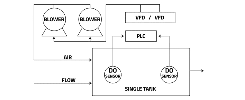
To save the most money and reduce the risk of fire drills, one recommendation is a solution comprised of dissolved oxygen sensors, a programmable logic control (PLC) and variable frequency drives (VFDs). See Image 1 for a single-tank system and Image 2 for a multi-tank system.
In a single-tank system, as loading increases, the dissolved oxygen (DO) sensor at the forefront will send a signal to the PLC to increase or lower the speed of the blower, depending on the reading compared to the set point on the PLC. The PLC then sends a signal to a VFD, which will slow down or speed up the motor on the blower(s).
In a multi-tank system, valves and a pressure transducer are added. There are DO sensors in each tank, and the PLC has set points for each tank. The PLC opens and closes the valves according to the dissolved oxygen needs of each tank.
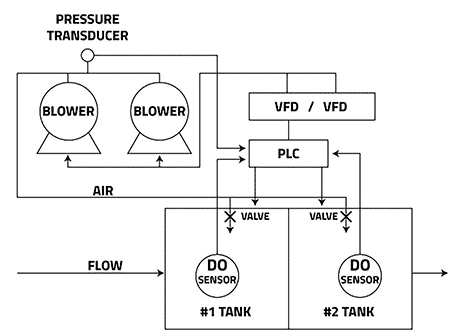
As the valves open, the pressure inside the air line is reduced. The pressure transducer’s job is to ensure the pressure inside the air line remains constant. When pressure drops in the air lines, the pressure transducer sends a signal to the PLC. The PLC then sends a signal to the VFD telling it to speed up and maintain airflow. When the valves close, pressure inside the lines goes up. The pressure transducer tells the PLC that the pressure is high. Then, the PLC sends a signal to the VFD to slow down the blower motor.
The controls in these two systems are all different and independent of each other; however, they work together in a cascading system. One affects the other, but their control loops are independent. If the influent in the system has changed, and there are now oversized blowers, consider implementing a control system. This choice will help keep better control of dissolved oxygen in the system and save money on energy costs.
