

Pumps are broadly classified into positive displacement pumps and centrifugal pumps. Positive displacement pumps have many different designs. There are three classifications for positive displacement pumps: rotary, reciprocation and linear. This article focuses on reciprocating pumps that operate using pistons/plungers.
Reciprocating piston pumps are one of the most common pumps and are used in many applications, such as pumping peanut butter in the food industry, pumping grease to lubricate machines, metering and transferring adhesive and dispensing oil in vehicle services. These reciprocating piston pumps are also called stick pumps, as the pumping section resembles a long stick that is intended for use with industry-standard containers.
piston pump
Concept & Theory
Two broadly used implementations of reciprocating piston pumps are the two-check and the shovel (priming piston) designs. A two-check piston pump (Image 1) is a reciprocating displacement pump in which two check valves (the piston check valve and the intake check valve) control the flow of fluid through the fluid section. Many types of check valves can be used in this design, but ball checks are most common.
The fluid displacement rod, or piston rod, connects internal pump components to a pump drive motor. It moves upward and downward with the action of a motor, transferring the motor’s power and motion to the piston assembly, displacing fluid out of the pump during both the upstroke and downstroke.
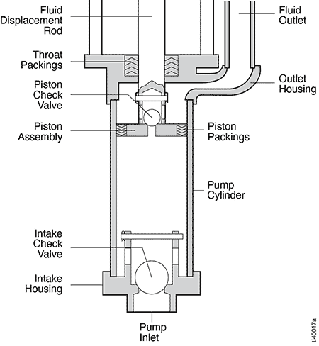
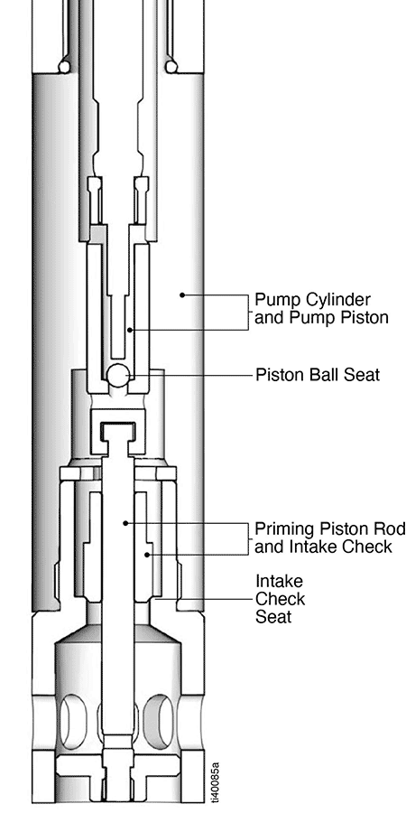
The piston check valve consists of the piston ball and piston seat. It operates in conjunction with the fluid displacement rod inside the pump cylinder, opening and closing to control the flow of fluid through the pump.
The intake check valve, or foot valve, also opens and closes with the action of the fluid displacement rod. Most intake check valves are ball-type checks, but flat plates are sometimes used instead. The two key components of the ball-type intake check valve are the intake ball and intake seat. The intake housing contains the intake check valve. The pump inlet is where fluid enters the pump.
Sometimes a bleed valve is used to vent or bleed air trapped within the fluid section because it is easier to prime the pump when there is no air inside it.
Operating Cycle
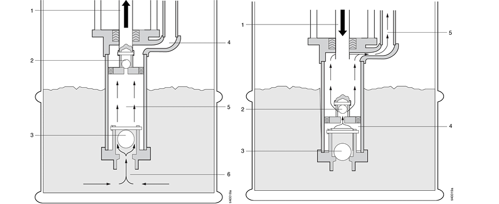
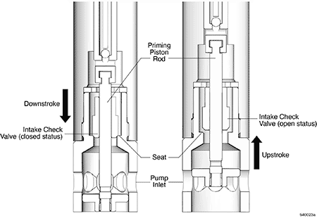
The two-check piston pump’s operating cycle consists of an upstroke and a downstroke.
Upstroke
- The motor pulls the fluid displacement rod upward.
- The piston check valve closes.
- The intake check valve opens.
- As the fluid displacement rod moves upward, fluid above the piston check valve in the pump cylinder is forced through the fluid outlet.
- A low-pressure area is created inside the pump cylinder below the piston assembly.
- Atmospheric pressure pushes the fluid from the supply container, past the open intake check valve and into the pump cylinder. Fluid then fills the volume of the pump cylinder.
Downstroke
- The motor pushes the fluid displacement rod downward.
- The piston check valve opens.
- The intake check valve closes.
- The trapped fluid inside the pump cylinder that was loaded during the upstroke flows through the piston check valve.
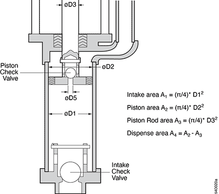
Balanced Displacement in Upstroke & Downstroke
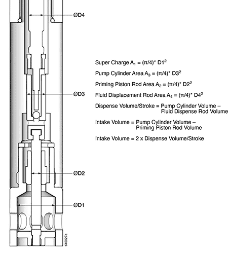
For the pump to dispense in both strokes, intake area A1 needs to be twice the dispense area of A4. The dispense area of A4 is calculated by finding piston area A2 and fluid displacement rod area A3, then subtracting area A3 from A2. It is also important to have more intake volume than the volume per cycle (both upstroke and downstroke). It is general practice to keep the intake check valve ball diameter larger than the piston check valve ball diameter. When the area of A1 is twice the area of A4, the pump is balanced for both the upstroke and downstroke.
Pump Drive Power Requirement
When a pump tries to build pressure, the force required by a pump drive (typically an electrical motor or a pneumatic cylinder) is equal to the pump pressure multiplied by the dispense area plus the seal friction. The moving components drive friction and the fluid friction due to viscosity.
Priming Piston Pumps: Components
Priming piston pumps are reciprocating, two-check displacement pumps that include a priming piston assembly, also known as a shovel, at the bottom. These are designed to pump viscous fluids and fiber- or chunk-filled materials more efficiently than standard two-check piston pumps.
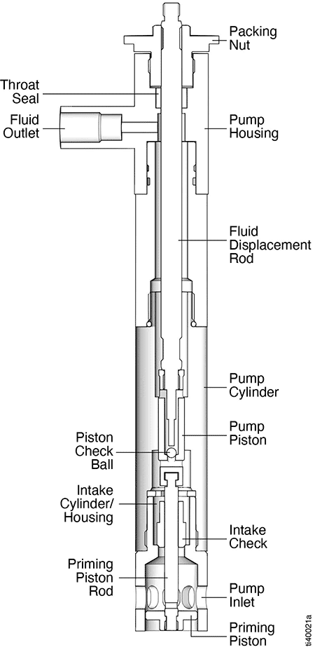
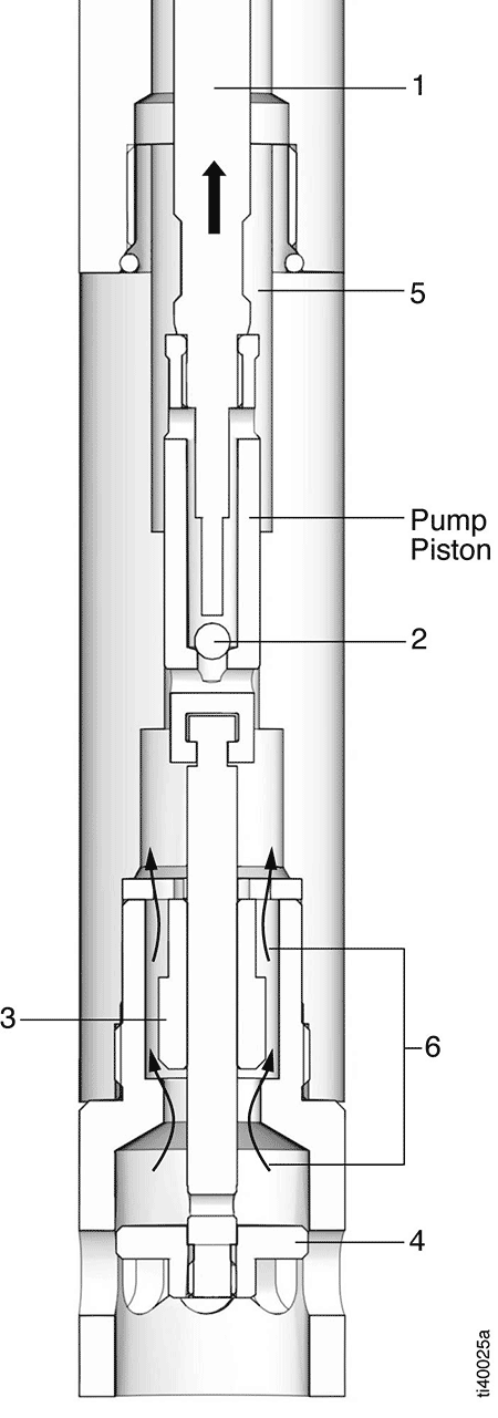
Image 5 shows the components of a priming piston pump. Priming piston pumps contain the same basic components as standard two-check piston pumps and function essentially the same way.
These components function as follows:
- The priming piston loads fluid through the intake cylinder, past the intake check valve and into the pump cylinder during the upstroke. Various designs of priming pistons are used depending on the type of fluid being pumped.
- The priming piston rod connects the priming piston to the bottom of the fluid displacement rod and to the pump piston.
- The intake cylinder contains the priming piston assembly, the priming piston and the priming piston rod.
- The design for the intake check valve (Image 6) includes a valve mounted on the priming piston rod and a stationary seat that is part of the intake housing. The check valve components are designed so the seating surfaces are always properly aligned.
Priming piston pumps require a positive fluid pressure to load. Because these pumps are used with highly viscous materials, they require the use of a more complex feed method than some other types of pumps. The positive fluid pressure required for loading by priming piston pumps is created using inductors, rams or follower plates (Image 7).
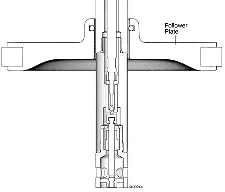
Heavy follower plates float on the surface of the fluid to be pumped. The weight of the follower plate exerts a positive pressure on the fluid, pushing material into the shovel, which primes the pump.
Operating Cycle
The priming piston pump’s operating cycle is similar to that of the standard two-check piston pump. It consists of an upstroke and downstroke. During upstroke, the pump components work as shown in Image 8.
Upstroke
- The motor pulls the fluid displacement rod upward.
- The piston check ball closes.
- The intake check valve opens.
- The priming piston is pulled up into the intake cylinder.
- As the fluid displacement rod moves upward, fluid above the pump piston (5) in the pump cylinder is trapped, forcing half of the fluid out of the pump through the fluid outlet per cycle.
- The priming piston and positive pressure push the fluid from the supply container past the open intake check valve and into the pump cylinder. Fluid fills 100% of the volume of the pump cylinder, minus the priming piston rod volume.
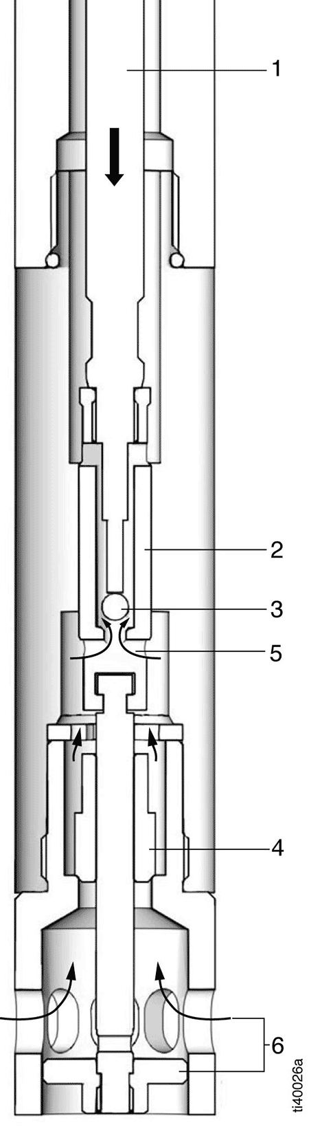
During downstroke (Image 9), as the inlet check valve is driven down by friction with the priming piston rod, it chops through the fluid material, then seals against the seat. Fluid pressure above the check valve helps seat the valve, ensuring a complete “chop and check.” Half of the fluid trapped above the intake check valve is displaced from the pump by the descending displacement rod.
Downstroke
- The motor pushes the fluid displacement rod downward.
- The pump piston moves downwards.
- The piston check ball opens.
- The intake check valve closes.
- Fluids above the intake check move from the intake cylinder through the piston check ball to above the pump piston, dispensing half through the fluid outlet. The other half of the fluid transferred through the piston check valve is displaced out of the pump with the next upstroke.
- As the priming piston moves downward, it creates suction for fresh fluid to be pulled inside through the pump inlet.
Balanced Displacement in Upward & Downward Stroke
The pump is designed to dispense an equal volume of fluid during both the upstroke and the downstroke. It is achieved by having the intake volume be twice as much as the dispense volume. In Image 4, with the area equations, volumes are calculated by multiplying the area of each of those components by stroke length.
Super charge volume at the intake housing is usually kept at 1.5 times the intake volume to continuously feed the pump.
Pump Drive Power Requirement
In priming piston pumps, in addition to pressure on the pump piston, there is pressure on the priming piston during upstroke, unlike the two-check pump design. In a downstroke, there is no pressure on the priming piston. Therefore, in electrically operated pumps, the current drawn is higher during the upstroke than during the downstroke.
When determining the required motor power to drive the pump, consider the pressure on the pump piston plus the pressure on the priming piston, the seal friction, the various components’ drive friction and the fluid friction due to viscosity.
Sealless Pump Design
As shown in Image 11, several areas must be sealed for the pump to build pressure. Depending upon fluid compatibility and pressure, traditional rubber/plastic seals may be used. Another option for sealing between these components is a hardened, precision ground, match-honed alloy steel. With a metal-to-metal clearance of .0002 inches, this will seal oil, such as ISO 32, up to 3500 pounds per square inch pressure. In addition, the piston ball seat and intake check seat can be lapped to hold pressure. This eliminates soft seals, replacing them with a metal-to-metal seal.
Wear-Resistance Coatings/Materials
To enhance the life of metal-to-metal sealing, various hard coatings can be added using a physical vapor deposition coating process. This creates a thin layer of hard coating on the surface and subsurface of the components. If the pump media needs a more aggressive seal, components can be made out of full cemented carbide to further enhance wear resistance and durability.
